Digital Photo Frame
Difficulty
Sight & Sound
Summary
Use our new WiFi UNO and 240 x 320 TFT screen!
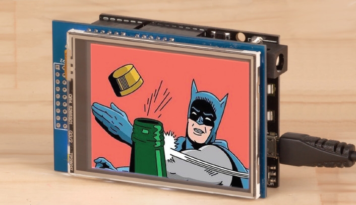
Share your memories or get the latest in memes automatically with this Wi-Fi enabled Photo Frame. Using our newest UNO with Wi-Fi board and a 320x240 touch screen display, simply provide a list of JPEG links and the photo frame will rotate through and display them automatically.
Can be used with the popular service IMGUR to get daily content automatically.
Table of Contents
Future Improvements
There is plenty of improvements that can be done; here are some shoutouts if people want to contribute to; and we love pull requests.
- The screen is 320x240; but our images from imgur are 320x320; meaning 80pixels must be clipped off the end. Instead of clipping it off the end, it would be great to calculate this beforehand and clip it evenly by 40 each side, so that the images are more centred in the photo frame.
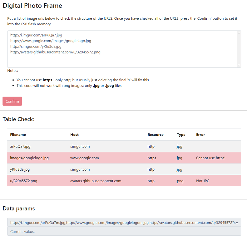
- The website is basic; we'd love to jazz it up a bit, maybe provide a bit of input validation and css effects.
- Provide a way to submit just an entire imgur album; Due to the limitations of the module it won't be able to do gif images but it should be able to rotate through the rest of the album; such as "most popular" albums.
- Google photo integration would make a great desktop reminder for your most recent holiday photographs.
Further reading
Web Fundamentals
APIs
Decoding
Similar projects you may be interested in


