.png?branch=prod_main)
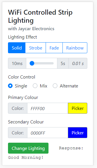
More or less a simple system conceptually; the esp provides a website that shows up like a makeshift Web-App on your phone. When you use the app to set the speed and colour of the strip lighting, the ESP will then process the parameters and activate the effects.
Current Effects
So far the effects we have done (as of 20/09/2019) are:
Rainbow:
(Cycles through colours, so Colour Options doesn't make sense)
Fade:
Mix: Fade between one to the other; Red->Purple->Blue;
Alternate: Fade alternatively, to black; Red->Black->Blue;
Strobe:
Mix: Flash with every second LED as the second colour;
Alternate: Half-n-half Strobe effects alternating flashes;
Check the github repository for the latest: @Jaycar-Electronics/WiFi-Controlled-Strip-Lighting
For this example we have 2 effects done; but we want more. Pull requests and code improvements through Github are well recommended and is a great way to learn. Contribute what you want, the worst we can do is correct it and send it back.
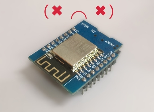
ESP8266 Configuration
The main work of this project involves the ESP8266 controller board
Before you begin
The XC3802 main board is used and has its own manual on how to enable it in the Arduino IDE; be sure to read and apply that first before trying to program the ESP; you can go do that now and come back to this project at any time :smiley:.
Board Settings
We are using pin D7 to control the Strip lighting; A quick point of reference (for the programming segment later): D7 is not accessed through the literal number 7 but instead by the designator D7.
Thus:
pinMode(D7, OUTPUT);digitalWrite(D7, HIGH);digitalRead(D7);
The literal D7 is only defined via the LOLIN(WEMOS) D1 R2 & Mini board setting, in the Tools->Board menu of the Arduino IDE.
In addition to this; we are storing our website on the ESP in flash memory, so we must use <SPIFFS.h> library which is included in the board management from above.
You should make sure you remember to set the flash size in the board settings, for this project we use size.
Tools
Board : WeMos D1 R2 & Mini
Flash Size: 4M (3M SPIFFS)
Port: (The port your ESP is connected to)
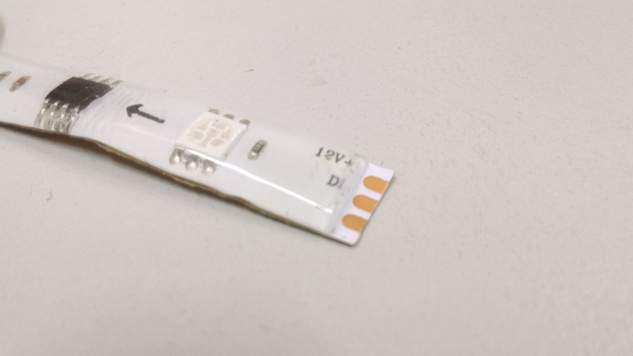
The circuit is a simple one; as we are using 12v source (as needed by the lights) we pass that through to the light circuit, and use a small 2n7000 FET to control the DIN line to the striplight.
Controller Board Layout
The general schematic is like this; note the orange wire.
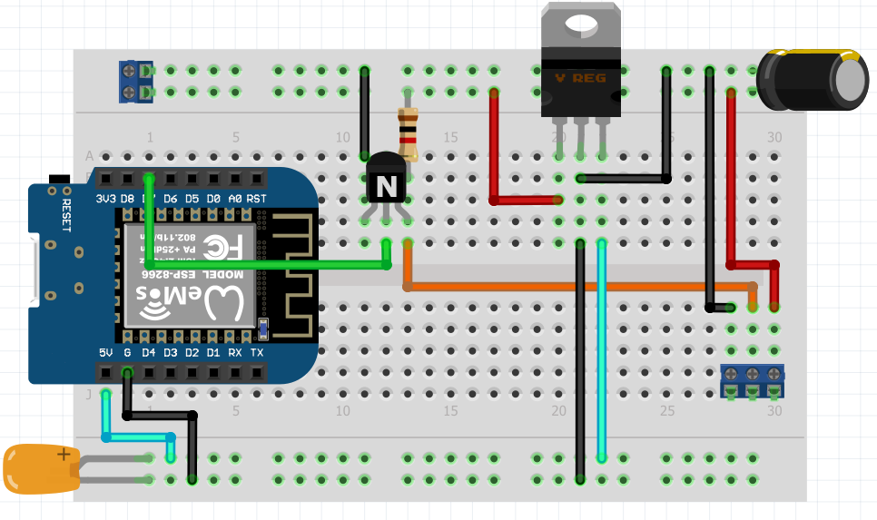
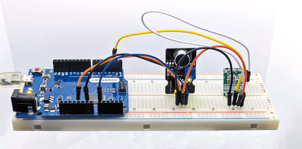
Above: breadboard version
.png?branch=prod_main)
It might start to look complicated but this is quite a simple circuit to pay attention to:
12V comes in via the connector on the left, with the top rail being +12v and the other being ground.
12V flows across the board to the other connector
GND follows around the underside of the board, and connects to the connector.
The middle SIGNAL-OUT connects to the top pin of the FET; and has the resistor between it and 12V.
the middle pin of the FET connects to D7 on the ESP8266.
There is a 7805 circuit that powers the ESP8266; this is a simple VIN, VOUT circuit, with capacitors on each of side.
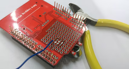
Depending on the PCB / veroboard that you've chosen to use for this project will determine how it's laid out; however if you're going with this tutorial and you're using the PCB board that we've supplied, you might find something a little bit like this:
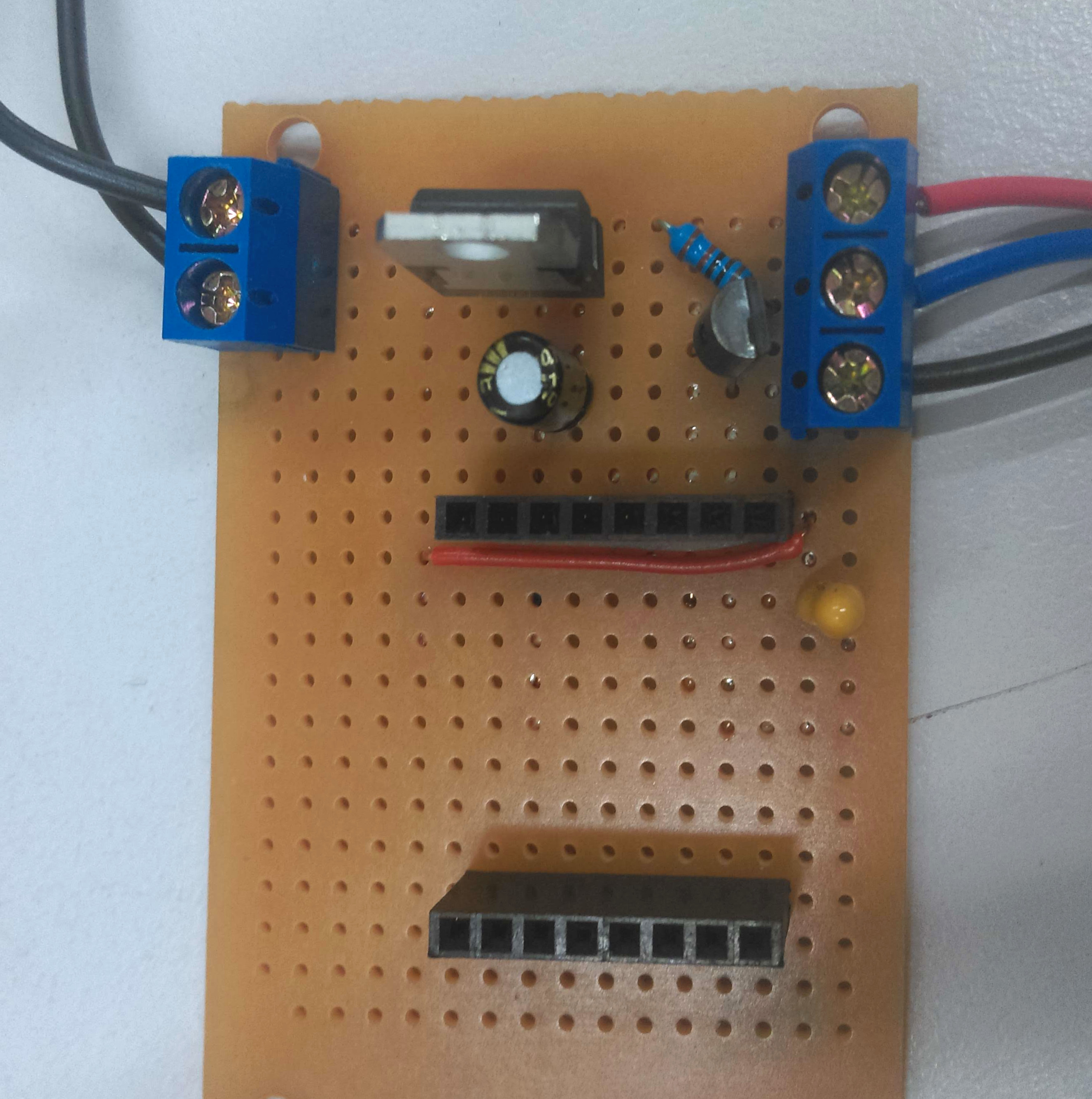
Given the connections on the underside of the board, there's a bit of work to get it so that it is not shorting itself out. Below is some photos of our board to help you, but try to follow along to make sure that things are connected as they should be. Haste makes waste.
The last photo of this segment is flipped so that you can see how it corresponds to whats under the board; make sure you do not copy this image, it is just for reference so you can visualise where each connection is going.
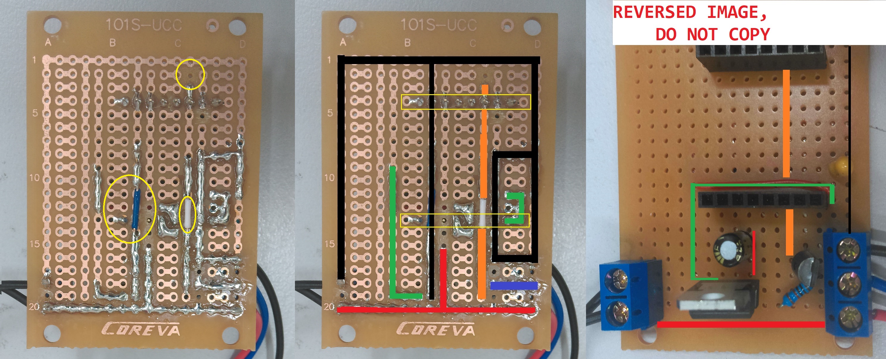
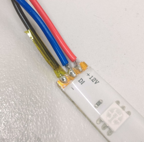
Follow the advice below so you can visualise it better; Note that there are bridges on both the and lines, so that they are not connected the pins underside. This is important and are highlighted in the yellow circles on the first image.
|
|
|---|
Black | Ground connection |
Red | 12V connection, connected to capacitor |
Green | 5V connection, coming out of 7805 chip |
Purple | Signal connection, resistor to 12v, coming from top pin of FET |
Orange | ESP signal connection, connected to D7 and middle pin of FET, |
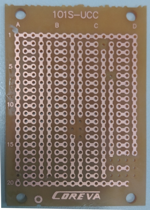
Below is a blank PCB that has had the correct traces cut; if you're still stuck you can copy this below by using a small knife to remove the traces, then simply place the above components and try to copy the above. If you are going your own way in regards to the PCB, just ensure to follow the images at the start of this section.
And finally, please do not connect 12v to your ESP, on any pin. Test and make sure with a multimeter that the 5V pin is 5V, and the other pins are not shorted.