Progress Bar

Skip to main content

Jaycar
...

Transistor Tester

Transistor Tester

Difficulty
TEST & TOOLS
Transistor Tester Main Image

Summary

This Transistor Tester is a handy tool; despite the name, it can test much more than just transistors! It can check the type and pinout of bipolar transistors and measure their gain, as well as examining Mosfets, diodes and LEDs to provide information like the pinout and forward voltage.

The best feature of this Tester is that it can help you work out the pinouts of unknown devices. However, it also gives you important parameters like the DC gain ( or hfe) of bipolar transistors or the threshold voltage (Vgs(th)) of Mosfets.

The Transistor Tester can detect and measure:

  • Bipolar transistors: pinout, polarity and ß (gain).
  • Logic-level Mosfets: pinout, polarity and gate-source threshold voltage.

  • Single/dual LEDs and diodes: pinout/polarity and forward voltage.

This project first appeared in the February 2025 Issue of Silicon Chip Magazine.

Materials Required

1Duinotech Leonardo r3 Main BoardXC4430
1Duinotech Arduino Compatible Prototyping ShieldXC4482
1Duinotech Arduino Compatible 2 X 16 LCD Screen Display with ControllerXC4454
310k Ohm 0.5 Watt Metal Film Resistors - Pack of 8RR0596
31k Ohm 0.5 Watt Metal Film Resistors - Pack of 8RR0572
140 Pin Female Header StripHM3230
1USB A to USB Micro B Cable 1.8mWC7724

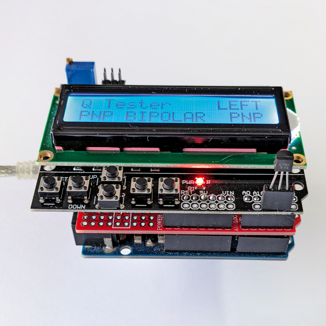
For LEDs, it will light them up so you can see what colour they are and how bright they are. It’s great for dual LEDs too, allowing you to test each element separately and see how it is connected.

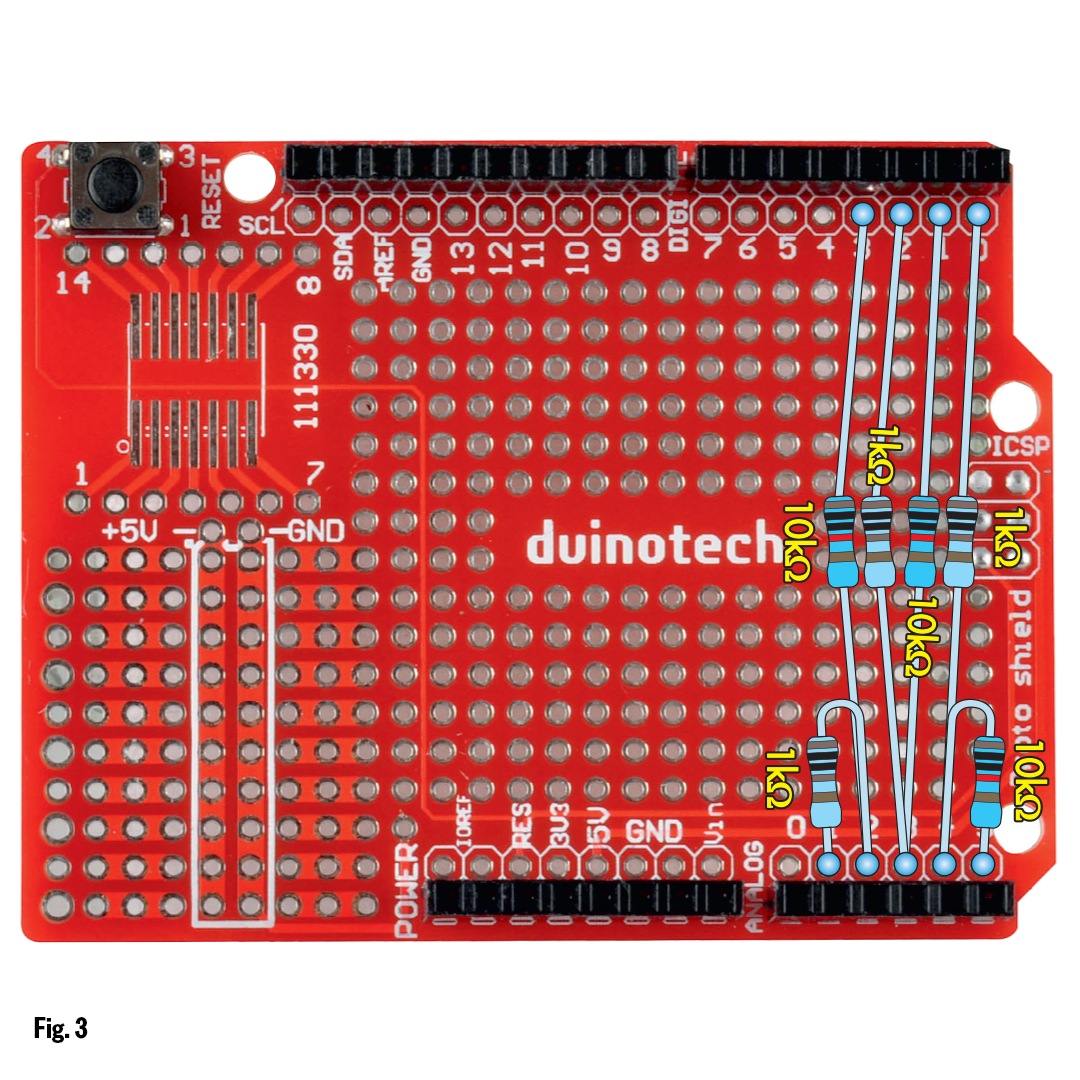
The Tester has a 16×2 character LCD screen on a ‘shield’ that also includes six tactile pushbuttons, making it easy for us to display information and accept user input. Fig.1 shows the circuit; note the connections around the six resistors and the test header.

main.png

it’s a simple circuit, but quite powerful when combined with the digital and analog peripherals of a microcontroller.

The test header is a three-way socket or similar so it can be used to connect a three-lead device such as a transistor. Two-lead devices can plug into any two of the three locations. The Arduino Leonardo microcontroller module connects to the LCD shield through fixed headers; the LCD shield’s pinout dictated most of the remaining pin choices we have made.

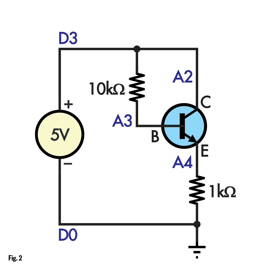
Fig.2 shows a possible configuration when testing of a typical NPN transistor such as a BC548. Pin D3 is taken high, effectively connecting it to 5V and supplying the base of the transistor via a 10kO resistor. Next, pin D0 is taken low, connecting the emitter to circuit ground via 1kO. Finally, pin A2 is taken high, directly connecting the collector to 5V.

fig_2.png

When testing an NPN transistor, this circuit is formed by setting various pins to a high or low level, or high-impedance (those pins are not shown). It can measure the voltages to determine the current through the resistors and thus different component leads.

We can then measure the voltage at the A3 and A4 analog inputs using the Leonardo’s 10-bit ADC (analog-to-­digital converter) peripheral. With those voltages, we can establish that the base sits around 0.7V above the emitter and that the current through the 1kO resistor (and thus emitter) is much greater than the current through the 10kO resistor and transistor base.

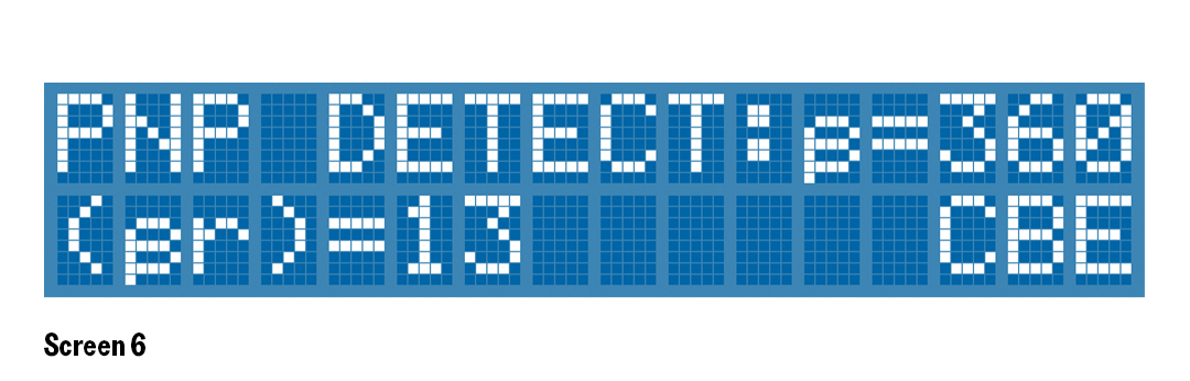
From that information, we can determine that the connected device is an NPN transistor with the pinout as noted. We can also calculate its DC gain from the ratio of the emitter and base currents. This is just one set of connections that the Tester can make. The Arduino can set any pin to be an input, meaning it is in a high-­impedance state; that means that it is effectively disconnected from the circuit. So we can probe individual pairs of pins in isolation, which we do to work out the potential location of PN junctions, as found in diodes or transistors.

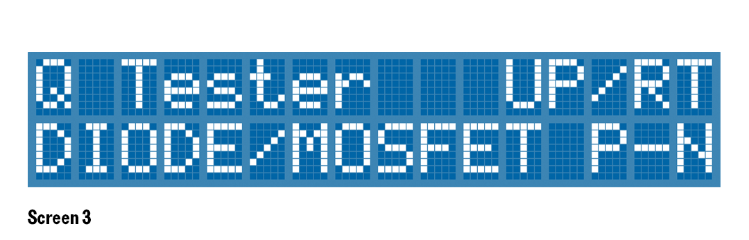
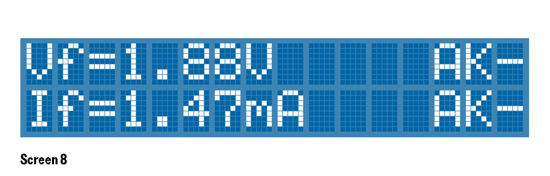
We don’t have space to describe all the internal operations in detail, but the Tester starts by probing pairs of pins to suggest what devices might be connected based on the PN junctions present. The initial tests use only the 10k resistors, so minimal currents are applied to connected devices. The user can then press one of the buttons to run a specific test to further characterise a connected device such as a transistor, diode or LED. Table 1 has some more details on the initial and detailed tests and the buttons used to perform them.

Component

Initial test

Button

Specific test procedure

Bipolar transistor

Check for two PN junctions (base-emitter and base-collector)

LEFT

Check polarity and  in different configurations and confirm pinout based on higher  value.

Mosfet

Check for one PN junction (body diode)

RIGHT

Check which polarity switches on Mosfet and confirm threshold voltage and polarity.

Diode

Check for one PN junction

UP

Measure forward voltage, display test current and confirm pinout.

Single LED

Check for junction with Vf higher than a silicon diode

UP

Light up LED, measure forward voltage, display test current and confirm pinout.

Dual LED

Check for two junctions with Vf higher than a silicon diode

UP and DOWN

Light up LED, measure forward voltage, display test current and confirm pinout. UP measures one junction, DOWN measures the other.

For example, potential LEDs and diodes are checked by measuring the voltage between two pins while ignoring the third. If the voltage is between 200mV and 750mV, it could be a silicon or schottky diode. If the voltage is higher (but less than 5V), it’s likely a light-emitting diode (LED).

Multiple LEDs are found by scanning the various pin combinations. Thus, common-anode, common-cathode and dual (back-to-back) LEDs can be identified and their pinouts confirmed.

A Mosfet is initially detected as a single diode, which is the body diode between the source and drain. Assuming that the other pin is the gate, it is then just a matter of checking whether it is a P-channel or N-channel Mosfet by driving the gate high or low to see if the Mosfet switches on.

Note that this only works for Mosfets with threshold voltages comfortably under 5V. Non-logic-level Mosfets usually have a threshold around 4V and are switched on fairly hard by 4.5V, so while it’s possible or even likely they would be detected correctly, it isn’t guaranteed.

A resistor might be identified as a back-to-back LED, since it will conduct in both directions. A resistance reading is also provided for this reason.

In addition to the LCD shield, we used a prototyping shield to simplify construction, as it looks much neater and is easier to follow. Check Fig.3 before soldering the resistors in place to match.

fig_3.png

This shows how we soldered the resistors to the prototyping shield. The circuit we have used lends itself to a tidy protoboard layout.

We used a short section of socket header soldered to the LCD shield to allow components to be plugged in for testing. You might consider clip leads or some flying leads to a breadboard as an alternative. Plug the three shields together once all the components are fitted.

You must use a Leonardo for this; an Arduino Uno or Mega won’t work because both those boards use the D0 and D1 pins for serial communications.

You’ll need the Arduino IDE to load the software. The LiquidCrystal library might need to be installed; this can be done from the Library Manager. We used version 1.0.7. The sketch folder includes the lcdkeys.h file for interacting with the buttons on the LCD shield.

Choose the Leonardo board and its serial port and upload the sketch. You should see a splash screen like Screen 1, after which the display should indicate that nothing is detected (Screen 2). If something is detected, you might have a wiring error!

screen_1.png
screen_2.png

Screens 1 & 2: the splash screen and idle screen are seen here. If you don’t see the idle screen (Screen 2) when nothing is connected, there may be a wiring problem.

The Tester tries to be as smart as possible while still allowing the user to select what tests to run by pressing suggested buttons. The pinout is displayed from left-to-right, matching the order on the test socket.

Try not to touch the leads while the test is happening. Fingers can pass enough voltage to switch on the gate of a Mosfet, which would alter the results. We tried out the Tester on numerous common devices, but we can’t predict what it might display for unusual ones.

Screens 3–8 show the results of connecting different devices to the test header, followed by pressing the suggested button. Screens 3 and 4 show a 2N7000 N-channel Mosfet being tested. The RIGHT button gives the report shown in Screen 4.

screen_3.png
screen_4.png

Screens 3 & 4: a Mosfet’s body diode is detected although the Tester cannot immediately determine which type it is. Running different tests with the UP or RIGHT buttons can narrow down the choices.

Screens 5 and 6 are the readings for a BC558 PNP transistor, with a press of the LEFT button resulting in Screen 6. Such a transistor can still work (albeit poorly) even if the collector and emitter are reversed, so we pick the arrangement with the highest  value; the reverse value is shown on the bottom line for comparison.

screen_5.png
screen_6.png

Screens 5 & 6: the text at lower right in Screen 5 indicates the relative location of the PN junctions in the part. In this case, they happen to match the connected PNP transistor. Screen 6 shows the device’s pinout at lower right.

A yellow LED shows Screen 7, then Screen 8 when UP is pressed. You’ll also see the LED light up while the UP button is held, with brief flashes off as other scans run. The current display on the bottom line alternates with a calculated resistance value, which will be useful if a resistor is connected.

screen_7.png
screen_8.png

Screens 7 & 8: if a dual LED is connected, Screen 7 will show the type (common cathode, common anode, etc) and the respective pins. Use UP and DOWN to probe the individual LED devices.

If you have a dual LED of any sort, the DOWN button can be used to scan the second LED in the package.

Similar projects you may be interested in

TEST & TOOLS
How to remove Header pins
Difficulty

TEST & TOOLS
Personal Weather Station
Difficulty

Installing and Setting Up the XC0440 Weather Station
TEST & TOOLS
Installing and Setting Up The XC0440 Weather Station
Difficulty

TEST & TOOLS
IR Helper
Difficulty