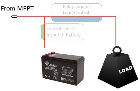
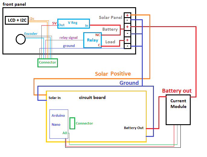
There's one main diagram here that needs explaining and it's the system layout.
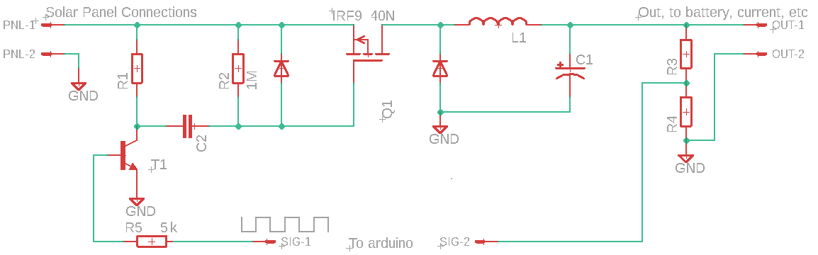
Starting from the left solar panel connectors, we designate positive and negative as connections one and two from PNL which connects straight to the source pin of our mosfet; the IRF9540N.
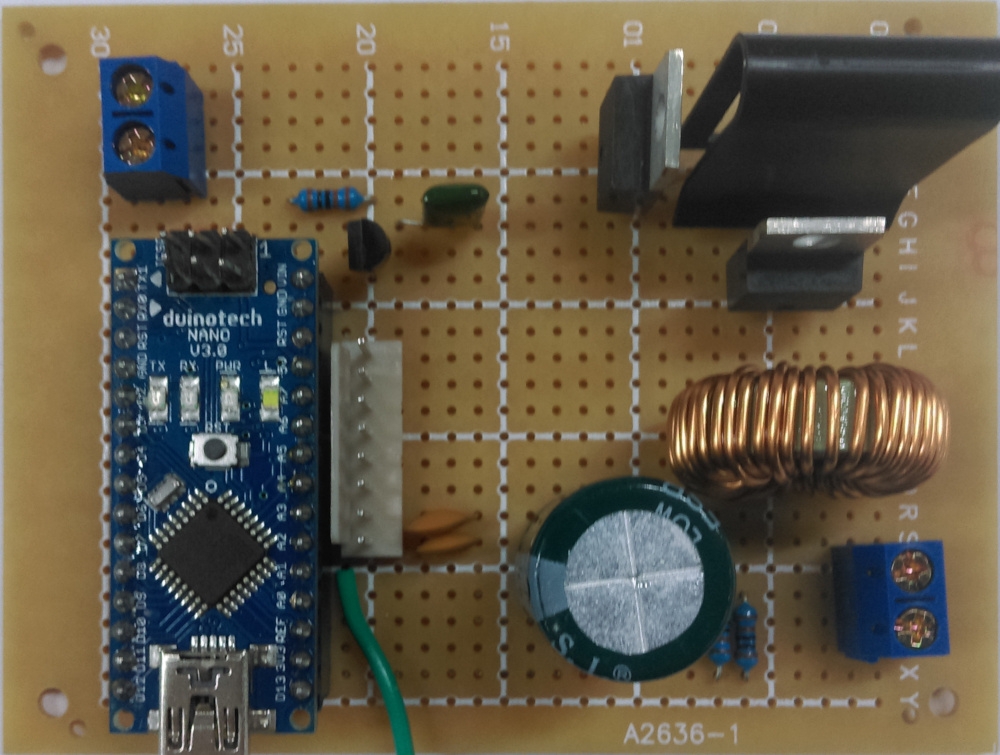
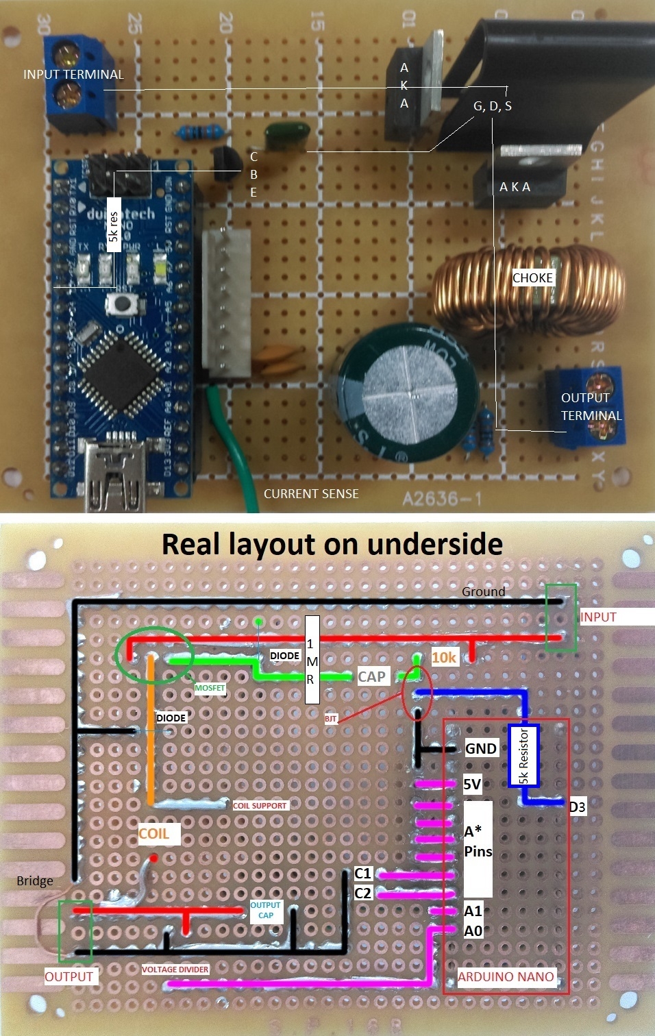
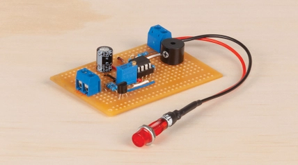
The IRF9540N (from here on, just 'IRF' for short) is the heart of this project; Which is why we cover it with a heat-sink. The core amount of power will be flowing through the mosfet depending on the signal from the arduino nano.
Our SIG-1 from the arduino is the square wave, flowing into our BC547 transistor; this is used to amplify the signal from the arduino flowing into the mosfet; -- if you're not too keen on the understandings of how transistors and mosfets work, We'd highly recommend you buy yourself a nice oscilliscope, some resistors and transistors, and see for yourself with how they work. In our case; if you look at the IRF Datasheet you will find the Gate threshold voltage to be between -2 and -4 volts (note the minus); theoretically, "at a voltage between -2 and -4" the gate will drop and the mosfet will begin to "turn on" and allow current to pass though (onwards to the battery).
We don't have a -2 to -4 volt source; we do have a 5v square wave and a capacitor, which will have to do. If we charge up a capacitor, once the capacitor is charged at 5V, dropping to 0 will induce a negative voltage.
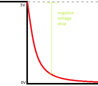
The only issue with this, from initial testing, was that it was not dropping fast enough and there wasn't a big enough "negative voltage" present on the gate of the mosfetto turn it on fully ( remember that -4 is the maximum voltage to START to conduct; consider it like a standard tap; you can slowly turn it on to START to drip; we wanted a bath-tub a minute..) - the BJT comes to the rescue.
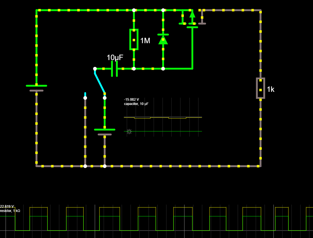
Instead of simply charging the capacitor to 5V from the arduino, the signal through the BJT gets amplified to some higher amount;then drops it just as fast, whipping the mosfet into action so that it can operate at full saturation and allow all the power to come through ( and to turn off when we want it to turn off). Observing this on a oscilliscope saved our bacon and allowed us to watch it behave correctly, before we continue to build.
Only other mentions on the GATE side of the mosfet is the use of the 1M resistor ( to 'tie' the gate to source voltage; The gate needs to operate with respect to the source, so instead of the capacitor only changing between 0-5, it's actually operating at 23v-18v, which is the -5v difference needed to turn on the gate; play around on falstad if you're not sure)
Then from the source to the drain of the mosfet, we output via an inductor (or Choke) and capacitor to give us smoother experiences on the battery side of things; There is a protection diode between the choke and the Mosefet so there is no harsh EMF voltage from the coil, and we have the final voltage measurement (through the voltage divider) and current measurement ( present on the battery terminals; see assembly instructions for positioning.) which gives us the power output from the system.
From that, there's the simplier connections below:
|
|
|
|
|---|
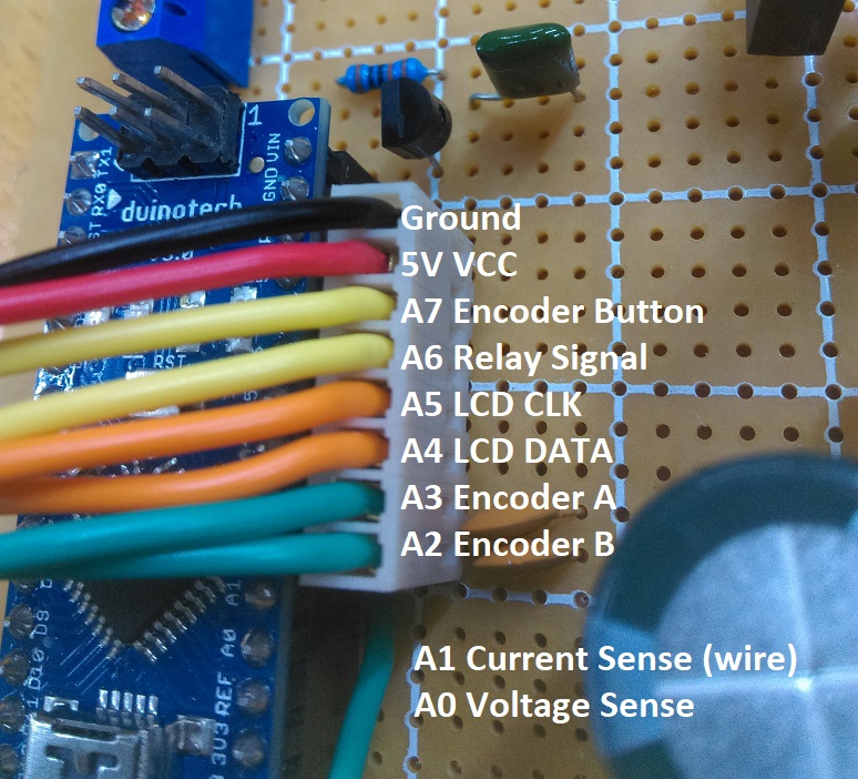
A0 | Voltage divider | | Voltage output from MOSFET |
A1 | Current output | XC4610 Current Sensor | Current output from MOSFET |
A2 | Encoder A | SR1230 Rotary Encoder | Encoder 'A' click |
A3 | Encoder B | SR1230 Rotary Encoder | Encoder 'B' click |
A4 | SDA | I2C Port Expander | Data signal going to screen |
A5 | SCL | I2C Port Expander | Clock signal to screen |
A6 | Relay Signal | XC4419 Relay Module | Activate relay when enabled |
A7 | Encoder Button | SR1230 Rotary Encoder | Button on encoder |
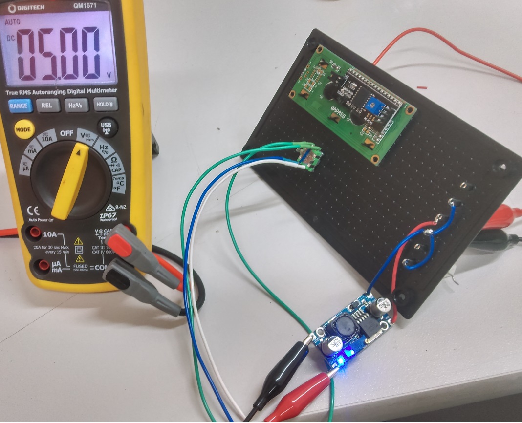
There is also a voltage regulator to power the arduino.
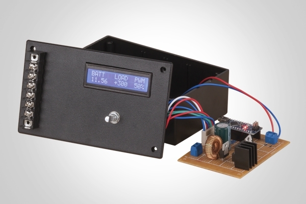
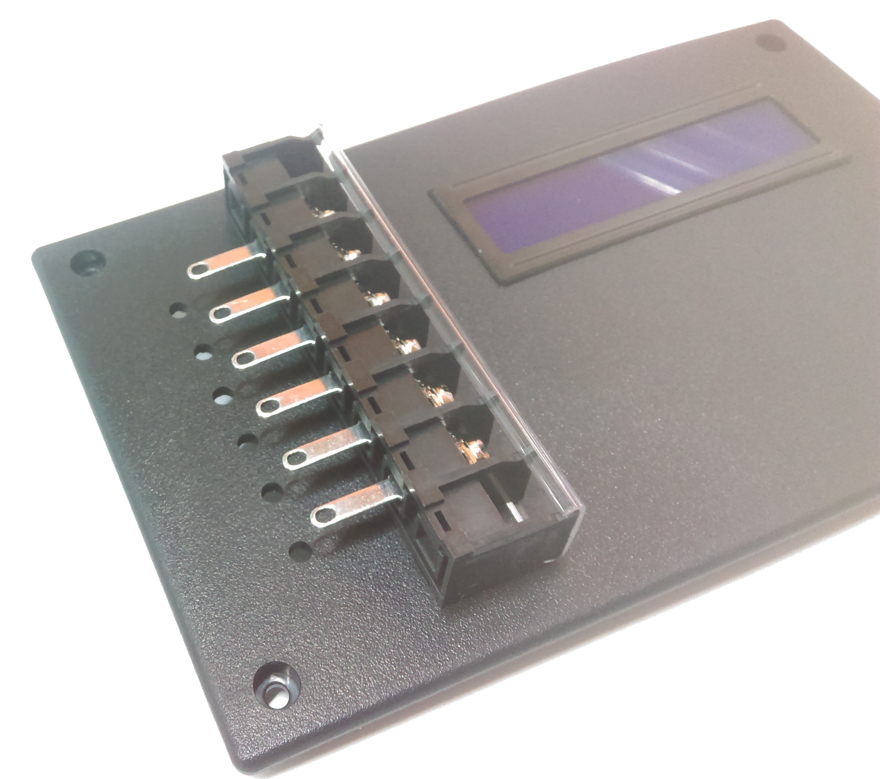
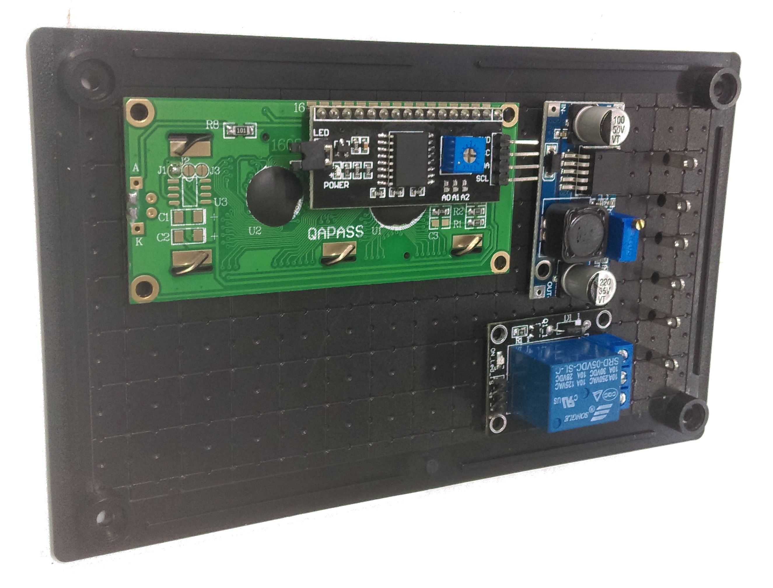
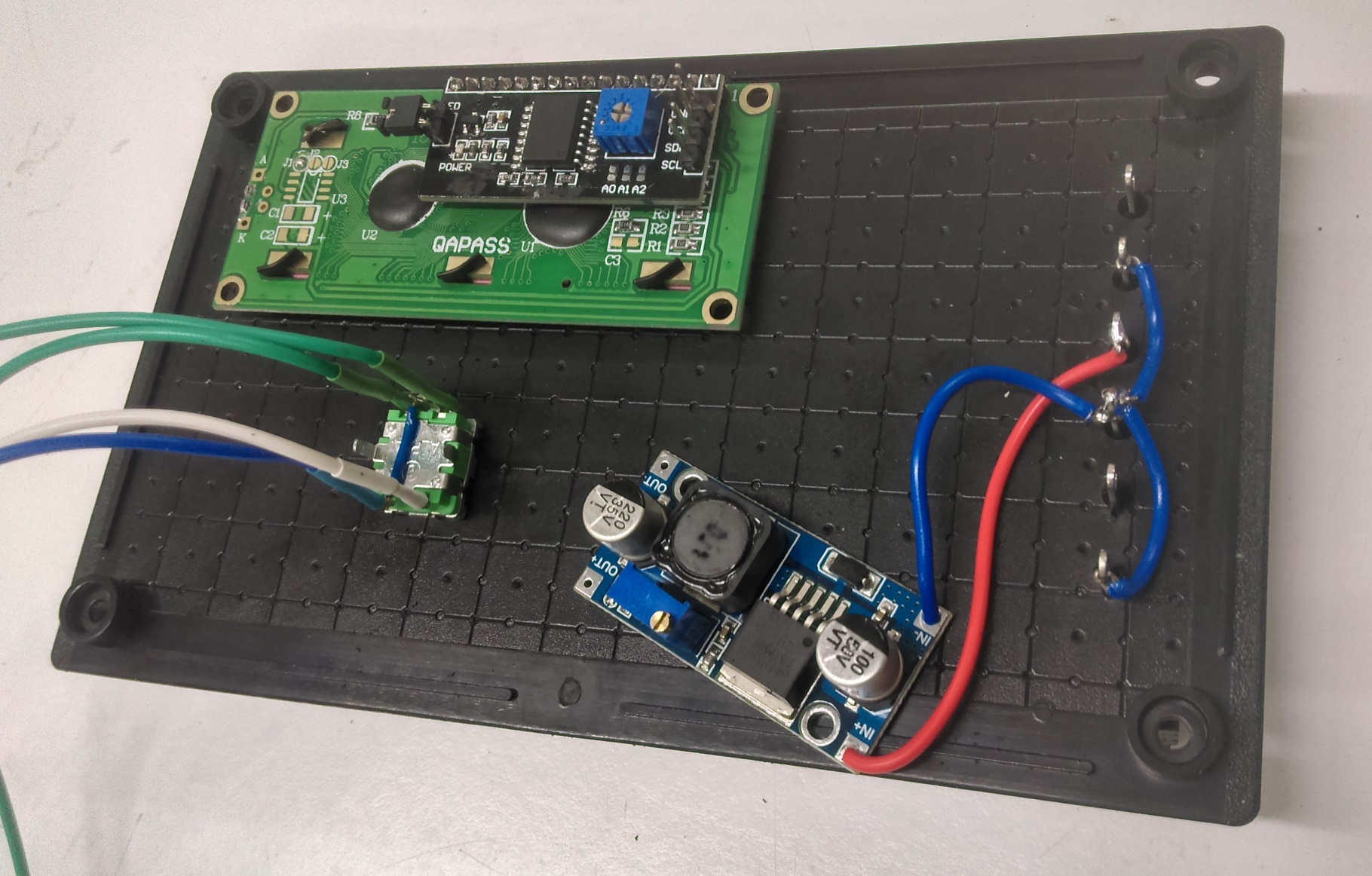
To make things easier, the relay, voltage regulator, current sensor, screen and encoder are all going onto the 'lid' of the HB6011 enclosure, which means we will have to use wires going between the 8 pin connectors to connect the functions of the lid to the main board.
The relay is used to controll power going to the load, allowing you to shut off when there's no daylight, or otherwise.