Duinotech Game Machine
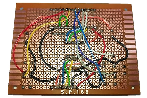
Summary
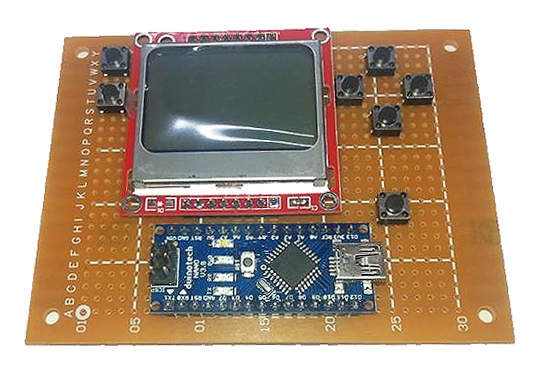
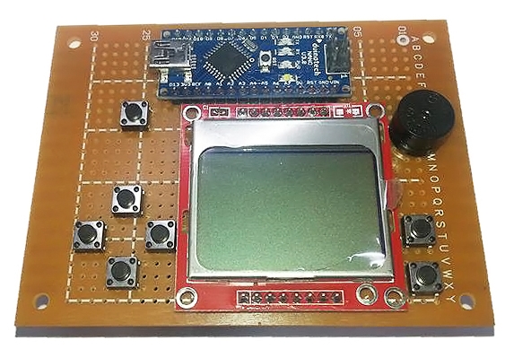
We found a little game project online at http://gamebuino.com, and with it being open-source, realised we could make our own version of it using duinotech parts. Even better, there's already a heap of games that have been created at https://github.com/Rodot/Gamebuino-Games-Compilation, and because it's based on Arduino, you can create your own games as well. There's a complete set of libraries for making your own games at https://github.com/Rodot/Gamebuino, too. And just to make sure you've got something to get started with, we've built a Tic-Tac-Toe game for it too.
Materials Required
| 1 | Arduino Compatible Nano Board | XC4414 |
| 1 | Arduino Compatible 84x48 Dot Matrix LCD Display Module | XC4616 |
| 1 | Duinotech Arduino Compatible Active Buzzer Module | XC4424 |
| 7 | 1.4mm SPST Micro Tactile Switch | SP0601 |
| 1 | Universal Pre-Punched Experimenters Board - Small | HP9550 |
| 1 | 10k Ohm 0.5 Watt Metal Film Resistors - Pack of 8 | RR0596 |
| 1 | 4.7k Ohm 0.5 Watt Metal Film Resistors - Pack of 8 | RR0588 |
| 1 | Rainbow Cable 16 Core - Sold per metre | WM4516 |
| 1 | 28 Pin Header Terminal Strip | HM3211 |
Table of Contents
Future Improvements
You might have looked at the official 'Gamebuino', and seen that it boasts a few more features than our version.
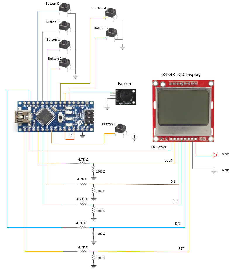
There is a backlight for the LED- this can be enabled by adding a 330 Ohm resistor between the D5 and LED pin on the LCD Screen- there are functions in the Gamebuino library to control a backlight on this pin. Otherwise, it can be permanently enabled by connecting the resistor between 5V on the Nano and the LED pin on the LCD Screen. Pin A7 can also be connected to a photo-resistor as a light sensor to allow automatic backlight adjustment- you can see the details of this in the schematics.
If you want portability, you could add a battery- even 3 x AA batteries (giving 4.5V) should be enough to run it happily. Alternatively, you could set up a Lithium Rechargeable battery to be charged from a XC4502 Lithium Battery Charge Module (just make sure the battery can handle the 1A charge current that the charger module can supply), and then use a XC4512 5V Boost module to run the Arduino Game Machine off the battery. You will probably need a switch like SS0852 Sub Miniature Slide Switch to turn it off to save the battery.
If you build more than one Arduino Game Machine, you can break out the I2C connections as a multiplayer link to allow multiplayer games.
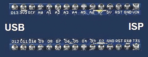
The most ambitious feature we've left till last- and that's the SD card slot. We've left it out not because it's hard to do, but because you have to reprogram the Nano's bootloader to allow it to be used. The official 'Gamebuino' allows HEX files to be stored on the card, and loaded by the bootloader by pressing the 'C' button on the initial menu. This actually overwrites the game on the device. To reprogram the bootloader, you need an ISP programmer such as XC4627 ISP Programmer with XC4613 ISP Adapter, and also manually create a board profile that uses this bootloader. You can find more information about this on the Gamebuino page and wiki.
Similar projects you may be interested in





.jpg?branch=prod&format=webp&width=428)
.png?branch=prod&format=webp&width=428)