Digital Compass
Summary
The follow extra items are required to complete this project:
- 1 x Micro-USB cable to suit Leonardo
- Straight Pin Headers (check what is supplied with the modules)
Magnetic declination is a term used to describe the deviation of the magnetic north from true north. This occurs because the magnetic poles are not exactly at the geographic poles. The Wikipedia page about Magnetic declination (https://w.wiki/9doF) has maps showing how this changes over both space and time.
That means the Digital Compass needs a correction factor to give accurate readings, and that factor will depend on your approximate location.
The Compass will display positive declination values as E (east) and negative values as W (west), as is the convention. The Compass shows declination values to one degree of precision, but note that it will jump around by a degree or two in normal use.
The easiest way to get a usable value is to perform a web search for magnetic declination with the name of your nearest city. To a rough approximation, the east coast of Australia is currently at around +10° (10°E) magnetic declination, with the west coast close to 0° magnetic declination.
Fig.1 shows the wiring diagram of the Digital Compass. The two critical modules, the magnetic sensor and 14-segment LED display, are supplied with power and connected to the microcontroller via a common I2C bus. The three switches are also connected to the controlling Arduino.
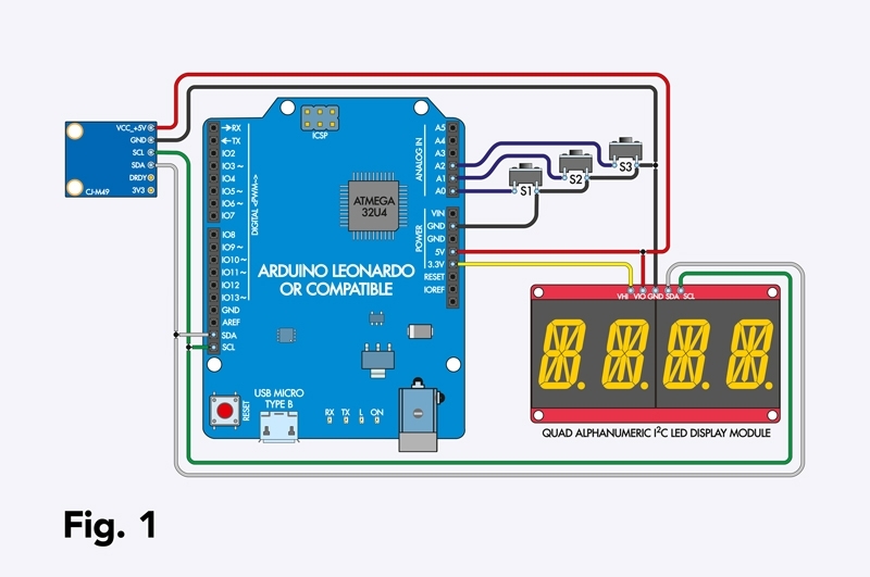
The chip on the compass module runs at 3.3V and the module has an onboard voltage regulator. This means that it expects the I2C bus to be at 3.3V. Due to how I2C works, the 5V Leonardo can interface to a 3.3V I2C bus, so there is no problem with the difference between the two in voltages.
The display module runs at 5V but has a separate pin for setting the voltage on its I2C pullups; we connect that to 3.3V to maintain compatibility with the compass module.
The processor provides the three tactile switches with pullup currents to hold the connected pins at 5V most of the time. It detects that they are pressed when the circuit is closed to ground, pulling those pins to 0V.
This circuit could easily be wired up with jumper wires on a breadboard. If you’d like something a bit neater or more permanent, you can follow our instructions for assembling the parts onto a prototyping shield.
Before soldering, note the pin markings on the underside of the modules. Refer to Fig.1, but remember that you could be working from the opposite side of the devices.
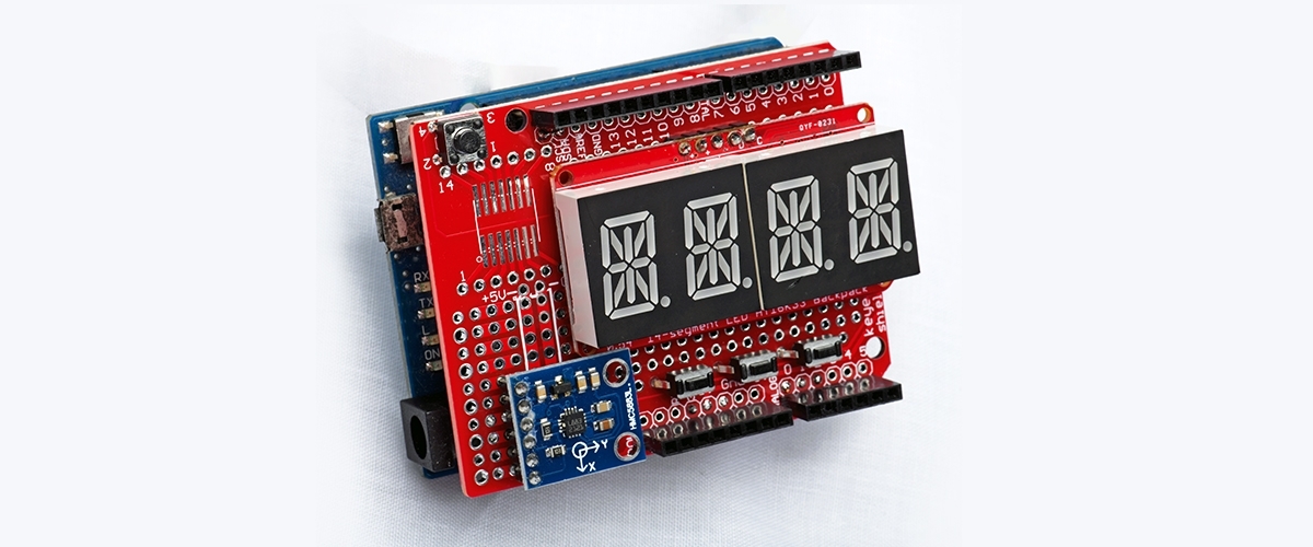
Start by soldering the display module to the prototyping shield. We aligned the module’s edge with the shield’s edge on one side, then used the topmost row of holes to retain the most space within the shield. Space the module vertically away from the shield to avoid short circuits.
The compass module solders to the row of pads intended to accept a DIP IC. Note how it very slightly overlaps the display module’s PCB. Because of the height of the 14-segment displays, it does not protrude. There appear to be a few variants of this module; we have used the larger version, but the smaller variant should fit just as well.
Next, solder the tactile switches in the space below the display. Ensure none of the leads are touching those from the other switches. The wiring is done underneath the shield to maintain a good appearance.
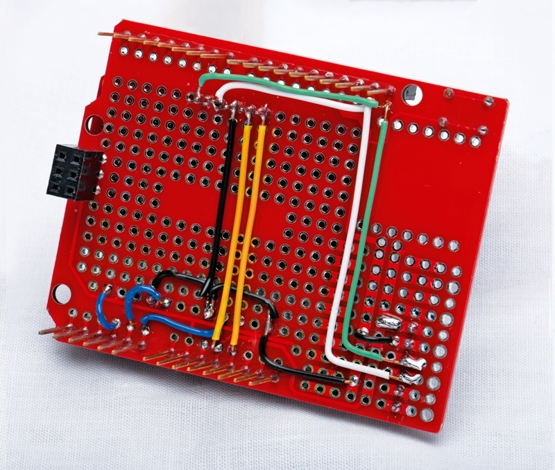
The wire colours we have used are much the same as in Fig.1, although we used yellow wires for the 5V connections to help them stand out from the red shield colour. The colours are merely a guide to assist assembly; you don’t have to use the same ones.
The blob of solder under the compass module is a 5V connection you can follow back via the PCB tracks. We also made some of the ground connections via PCB tracks.
Start by soldering the ground connections as shown in the photo of the shield’s underside. Follow with the blue wires to the switches. Each switch should now have a blue wire at one end and a black wire at the other.
Next, solder the 5V wire (and 5V blob) and one 3.3V wire. Then there are two SDA wires and two SCL wires for the I2C bus. Slot the prototyping shield onto the Leonardo, being careful to align all the pins correctly. We are using the SDA and SCL pins near D13, so this should also work with an Arduino Uno board, although we have not tested it.
The software operation is quite straightforward. The Leonardo’s processor reads data from the compass module, calculates a compass heading, then displays that on the 14-segment LED module.
We have bundled everything into a single sketch folder, including a basic library for the display module (the file is named XC3715.h) and a library for the compass sensor. The latter comprises the HMC5883L_Simple files from the same library (from James Sleeman) that Jim Rowe used in his 2018 modules article.
To program the Arduino, download the sketch from siliconchip.au/Shop/6/430 and unzip it, then open it in the Arduino IDE. Select the Leonardo board option and its serial port via the menus, then upload it. The serial monitor will report some debugging data once that process has finished.
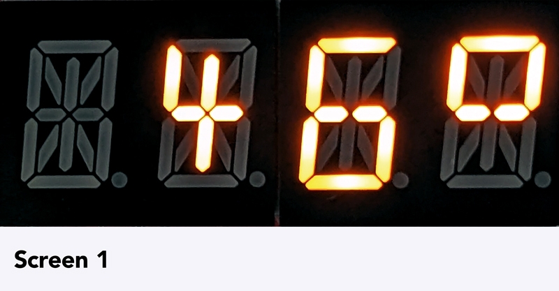
After a second or so, you should see a display in degrees (see Screen 1). The displayed bearing should increase if you turn the Digital Compass clockwise and decrease if you turn it anti-clockwise. If you don’t get that reading, check the wiring to the display.
If the bearing does not change, you might have a problem with the wiring to the compass module. The serial monitor will also display the bearing, so you can check that the compass module is working, even if the display is not.
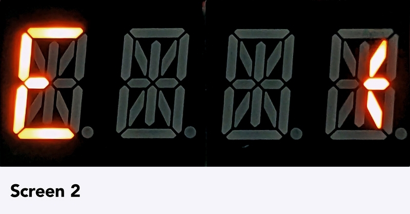
The default is to display a bearing in degrees, but pressing S1 (the leftmost button) will change to displaying a cardinal (N, NE, E, SE, S, SW, W or NW) compass point, which you can see in Screen 2. There is also a (somewhat squashed) arrow that will point north on the right-hand side of the display.
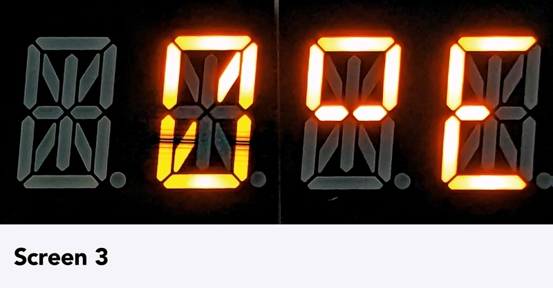
Pressing S2 or S3 will adjust the brightness; the chip on the display module provides 16 steps. If you hold S1, the magnetic declination is shown, and pressing S2 or S3 while S1 is held will adjust it, as shown in Screen 3.
You could either use a declination value from a web search or, if you know where north is, you could point the Compass north and manually trim the declination until the Compass reads 0°.
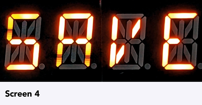
After 10 seconds, you might see SAVE flash up on the display (Screen 4). That means the current settings have been saved to EEPROM and will be retained if the Compass is turned off. The settings are reloaded when it is restarted.
This article appeared in the May 2024 issue of Silicon Chip Magazine. Check out their website for other project ideas: https://www.siliconchip.com.au/
Similar projects you may be interested in


