Resistor & Capacitor Tester
Summary
Here's another easy to build project similar to the LED tester, and using the same hardware. This project will try to work out whether it's connected to a resistor or capacitor and then show you the value (resistance or capacitance) of it. If it's a resistor, it'll also suggest the nearest resistor from the Jaycar range of ½W resistors. Of course, using off the shelf components, it's not a high accuracy device, but handy to have if you're sorting through your junk drawer and are having trouble with the colour codes. There's about ten solder joins that need to be made to complete this project.
If you've already built the LED tester, you can add the components onto the same proto shield, as the circuits use different pins on the Uno (but the same pins for the LCD).
Materials Required
| 1 | Duinotech UNO r3 Main Board | XC4410 |
| 1 | Duinotech Arduino Compatible Prototyping Shield | XC4482 |
| 1 | Duinotech Arduino Compatible 2 X 16 LCD Screen Display with Controller | XC4454 |
| 1 | 150 Ohm 0.5 Watt Metal Film Resistors - Pack of 8 | RR0552 |
| 1 | 1.2k Ohm 0.5 Watt Metal Film Resistors - Pack of 8 | RR0574 |
| 1 | 10k Ohm 0.5 Watt Metal Film Resistors - Pack of 8 | RR0596 |
| 1 | 150mm Plug to Plug Jumper Leads - 40 Piece | WC6024 |
The resistor values aren't critical, but the smallest one can't be smaller than 125R as this will overload the Uno's outputs. If you use different values, check the notes in the code about the changes that need to be made.
I used two plug-plug jumper cables as my probes, but you could just use any small wire (eg speaker cable) that is lying around. You'll also need a small piece of wire to make a connection on the Protoshield.
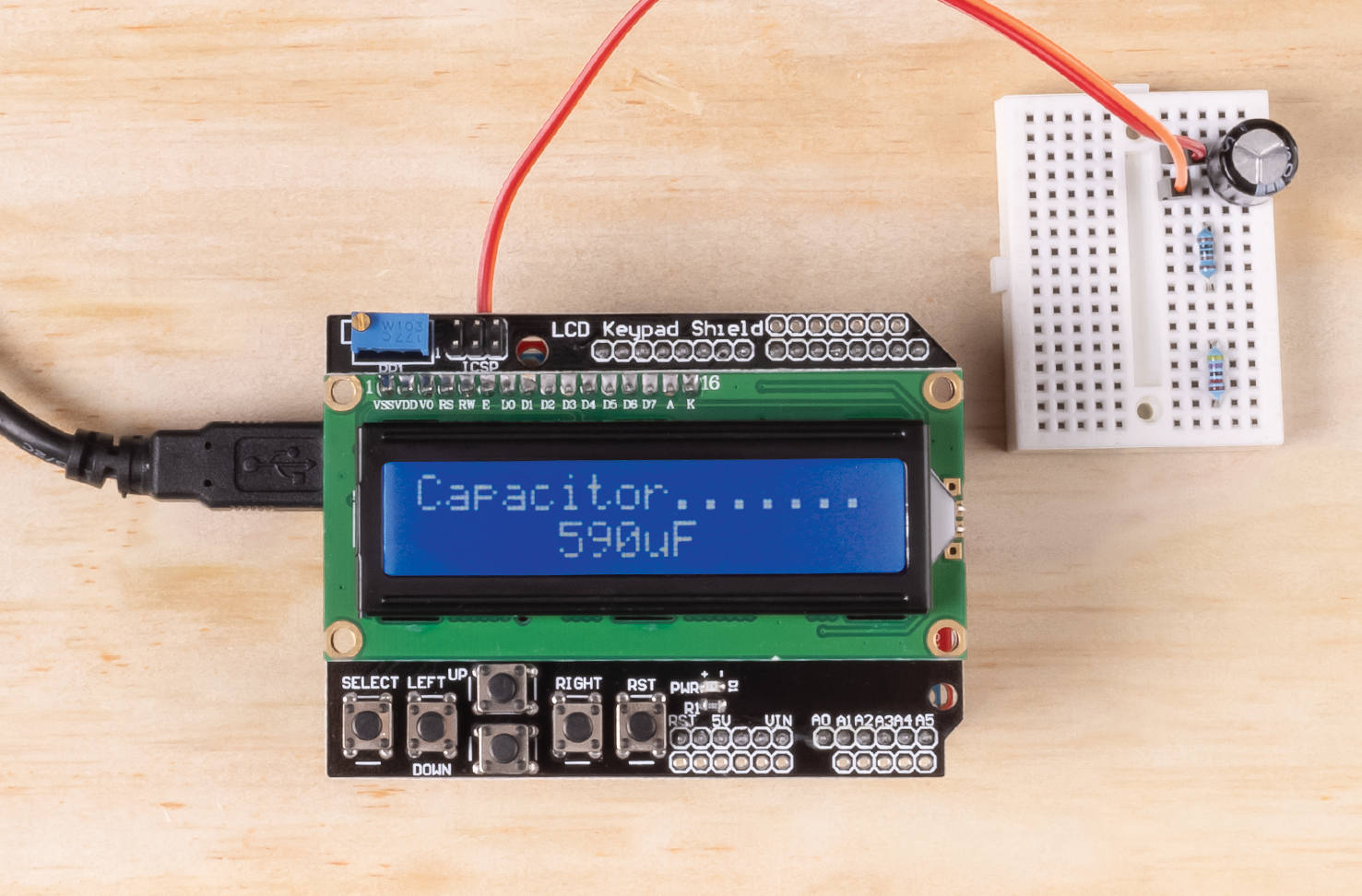
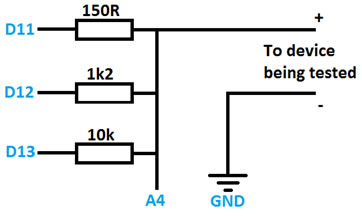
Apart from plugging the shields into the Uno, the hard part is soldering the three resistors and probe leads onto the proto shield. See the diagram and photo below.
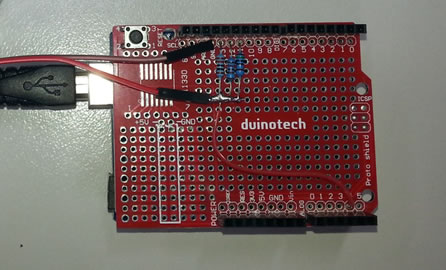
Once the resistors and wire have been soldered together, plug the Protoshield into the Uno, then plug the LCD Shield into the Protoshield (they should only go one way).
There aren't any extra libraries that are needed for this project as the 'LCD' and 'math' libraries are both included with the IDE. The code should work fine without changes on a Leonardo or Mega board if you have one of these instead. If you're using different resistors, you'll need to change the definitions of the R1VALUE, R2VALUE or R3VALUE constants. You can also change the pins here too. The code uses some of the functions from the LED tester sketch (such as the key handling), but is mostly completely different.
The component detector works by putting 5V onto the 10k resistor, and if A4 is anything but very close to 5V, then something is connected and pulling the analog reading closer to GND.
The routine for working out if the component is a capacitor or resistor works by assuming it is a capacitor, and discharging it (via 150R resistor to GND), then measuring the voltage on it, then charging it up again and measuring the voltage. If the voltage has changed, then it is a capacitor, if it hasn't changed, then it's a resistor.
To measure a resistor, the three test resistors are each set up as a voltage divider with the test resistor, and the voltage at the junction measured. The resistor which gives a reading nearest 2.5V is chosen (as this will give the best precision), and the resistor value is calculated using the voltage divider formula: R2 = (R1 x V2)/V1. This routine exits when it detects a very high resistance, assuming this means the test resistor has been disconnected.
The capacitor tester starts by trying to discharge the capacitor for half a second (the results are more accurate the less the capacitor is charged). The voltage on it is measured, then it is charged from 5V via the 150R resistor for 0.1s, then the voltage on it is measured again. The ratio between the two voltages gives the proportion of charge (towards fully charged) it has received. When this is combined with the 0.1s time, the time constant for the resistor-capacitor combination can be worked out, and this is simply divided by the resistor value to give the capacitance value. If the capacitor ends up nearly fully charge, then the measurement is not completely accurate, and the test is redone with the 1k2 resistor. The results are then converted to easy to read units, rounded and displayed. Similarly, if this routine detects a very low capacitance, it assumes the test component has been removed and returns to the main detect routine.
The two leads are simply connected to the leads of the component you wish to test. If the component is polarised (eg. electrolytic capacitor), then the lead attached to A4 should go to the positive side and the GND lead to the negative side. I've made the leads different colours to remind me of this. The tester should only be used on circuits that aren't connected to power, especially as the UNO's chip can easily be damaged by voltages more than 6V. Components in circuit may not read correctly, as they will be influenced by other components they may be connected to.
One day, I hope to combine all the functions of the two testers to run off the same sketch (and maybe the same leads). As built, the tester will measure resistance from 0R up to the Megohms, and capacitance from nanofarads up to near a Farad. With some changes to the resistor and timing values, this range could be expanded slightly, but this is mostly limited by the accuracy and internal resistance of the ADC on the UNO. When we get a colour LCD screen, perhaps the resistor colour codes can be added as well. I haven't added a component part number recommendation for the capacitor test routine, because there are so many different voltage rating and capacitor types, that a given capacitor value would probably match up with several part numbers. There's no reason this couldn't be added if you knew (for example) that you were always using 16V electrolytic capacitors.
/*	Arduino Resistor and Capacitor Tester

D13--10k---+--------------->  Positive probe
D12--1k2---+
D11--150R--+   +----------->  Negative probe
           |   |
           A4 GND

Resistor test by voltage divider- uses 3 different resistors to give auto-ranging.
Capacitor tester- Capacitance by time constant calculation, ESR by discharge and resistance test. (ESR not accurate so not displayed)
3 modes: Auto (on startup, or by pressing select)- tries to autodetect component and then measures
Resistor (press left)- assumes resistor and tries to measure resistance
Capacitor (press right)- assumes capacitor and tries to measure capacitance
*/

//ranging resistor pins and values: R1 should be lowest (use a decimal point to make sure they're floats)
//values aren't critical, but should be span a good range
//lowest value possible is 125R- lower would overload the pin. Max is probably 100K due to leakage etc.
//if you have a good multimeter, you can tweak these values as calibration

#define R1VALUE 150.0
#define R2VALUE 1200.0
#define R3VALUE 10000.0
#define R1PIN 11
#define R2PIN 12
#define R3PIN 13
#define AIN A4
#define MIDRANGE 512
#define CAPTIME 0.1

#include <LiquidCrystal.h>
#include <Math.h>

//pin defs to suit LCD Shield
LiquidCrystal lcd(8, 9, 4, 5, 6, 7);

//pin for buttons
#define KEYPIN A0

//button constants
#define btnRIGHT  6
#define btnUP     5
#define btnDOWN   4
#define btnLEFT   3
#define btnSELECT 2
#define btnNONE   (-1)

//Globals for display
//resistors in Jaycar 1/2 W range, part nos start at RR0524 for 10R
#define RCOUNT 121
long rvals[]={10,11,12,13,15,16,18,20,22,24,27,30,33,36,39,43,47,51,56,62,68,
75,82,91,100,110,120,130,150,160,180,200,220,240,270,300,330,360,390,
430,470,510,560,620,680,750,820,910,1000,1100,1200,1300,1500,1600,1800,
2000,2200,2400,2700,3000,3300,3600,3900,4300,4700,5100,5600,6200,6800,
7500,8200,9100,10000,11000,12000,13000,15000,16000,18000,20000,22000,
24000,27000,30000,33000,36000,39000,43000,47000,51000,56000,62000,68000,
75000,82000,91000,100000,110000,120000,130000,150000,160000,180000,
200000,220000,240000,270000,300000,330000,360000,390000,430000,470000,
510000,560000,620000,680000,750000,820000,910000,1000000};
int cdetect=0;    //variable for detected component 1=R, 2=C
int cselect=0;      //to force component selection 0=auto, 1=R, 2=C

void setup() {
	lcd.begin(16, 2);        //lcd
	lcdsplash();
	lcd.setCursor(0, 1);
	lcd.print("     Tester");
	delay(1000);
}

void loop() {
	waitconnect();     // wait till something is connected
	if(cselect){cdetect=cselect;}else{cdetect=detect();}    //goto selection if made, otherwise autodetect
	switch(cdetect){
		case 1:
		doresistor();
		lcdsplash();      //redo the splash screen in case it was written over
		break;
		case 2:
		docapacitor();
		lcdsplash();      //redo the splash screen in case it was written over
		break;
		default:
		doerror();
		break;
	}
}

void doresistor(){
	while(1){       //do it all repeatedly till the resistor is disconnected (see return; below)
		int a1,a2,a3,a,diff;
		float rdiv,rcalc,af;        //rdiv= Rof divider, rcalc is R of resistor under test, af is float version of analog reading
		pinMode(R1PIN,OUTPUT);
		pinMode(R2PIN,INPUT);
		pinMode(R3PIN,INPUT);
		digitalWrite(R1PIN,HIGH);
		delay(1);
		a1=analogRead(AIN);    //read with 1st resistor as voltage divider
		pinMode(R1PIN,INPUT);
		pinMode(R2PIN,OUTPUT);
		digitalWrite(R2PIN,HIGH);
		delay(1);
		a2=analogRead(AIN);    //read with 2nd resistor as voltage divider
		pinMode(R2PIN,INPUT);
		pinMode(R3PIN,OUTPUT);
		digitalWrite(R3PIN,HIGH);
		delay(1);
		a3=analogRead(AIN);    //read with 3rd resistor as voltage divider
		pinMode(R3PIN,INPUT);   //shut outputs down
		//find the resistor which gives an analog value closest to 512- middle of the range gives best accuracy
		a=a1;
		rdiv=R1VALUE;
		diff=abs(MIDRANGE-a1);    //assume it's R1 and then see if there's a better match
		if(abs(MIDRANGE-a2)<diff){ //R2 is better
			a=a2;
			rdiv=R2VALUE;
			diff=abs(MIDRANGE-a2);
		}
		if(abs(MIDRANGE-a3)<diff){ //R3 is better
			a=a3;
			rdiv=R3VALUE;
			diff=abs(MIDRANGE-a3);
		}
		if(a>=1022){     //open circuit, resistor has probably been detached, so go back to main screen, avoid div/0 error
			return;
		}else{
			af=a;
			rcalc=(af/(1023-af))*rdiv;
			lcd.setCursor(0, 0);
			lcd.print("Resistor:   ");
			lcdprintrval(rcalc);
			int i=rmatch(rcalc);     //find index of R that matches rcalc best
			lcd.setCursor(0, 1);
			lcd.print("Try ");
			lcdprintpartno(i);
			lcd.print("(");
			lcdprintrval(rvals[i]);
			lcd.print(")");
			delay(300);    //wait a bit so we get a steady display
		}
	}
}

int rmatch(float r){
	int k=-1;  //to store index of best match, default to -1
	float d=1e9;    //very big number, representing difference from matches
	for(int j=0;j<j++){
		if(abs(rvals[j]-r)<d){
			d=abs(rvals[j]-r);
			k=j;
		}
	}
	return k;
}

void docapacitor(){
	int alo,ahi;
	float esr;
	float c,ts,soc,t,ahif,alof,rvalue;
	lcd.setCursor(0, 0);
	lcd.print("Capacitor.......");    //measuring caps might take a bit longer, so change display
	while(1){       //stay in this loop until disconnected
		pinMode(R1PIN,OUTPUT);
		digitalWrite(R1PIN,LOW);    //R1 to discharge as much as possible
		pinMode(R2PIN,INPUT);
		pinMode(R3PIN,INPUT);
		delay(500);
		pinMode(R1PIN,INPUT);
		alo=analogRead(AIN);        //to read ESR
		digitalWrite(R1PIN,HIGH);    //turn on power to detect voltage drop across cap-probably not super accurate
		pinMode(R1PIN,OUTPUT);
		ahi=analogRead(AIN);        //difference with power on
		digitalWrite(R1PIN,LOW);    //R1 to discharge as much as possible
		if(ahi<alo){ahi=alo;}       //to avoid negative values
		esr=0;
		if(ahi<1023){
			esr=((ahi-alo)*R1VALUE)/(1023-ahi);
		}
		//measure voltage on cap, charge up for t, measure state of charge, convert to tc's, work out C knowing R
		digitalWrite(R1PIN,HIGH);    //charge it up
		alo=analogRead(AIN);        //to read capacitance
		delay(CAPTIME*1000);
		ahi=analogRead(AIN);        //to read capacitance
		digitalWrite(R1PIN,LOW);    //discharge (in case we need to do again)
		rvalue=R1VALUE;   //assume this is the one we're using
		if(ahi>1000){     //very high termination, probably get more accurate results with 2nd resistor
			rvalue=R2VALUE;   //assume this is the one we're using
			delay(500);     //discharge
			pinMode(R1PIN,INPUT);
			pinMode(R2PIN,OUTPUT);
			digitalWrite(R2PIN,HIGH);    //charge it up
			alo=analogRead(AIN);        //to read capacitance
			delay(CAPTIME*1000);
			ahi=analogRead(AIN);        //to read capacitance
			digitalWrite(R1PIN,LOW);    //discharge (in case we need to do again)
		}
		alof=alo;
		ahif=ahi;
		if((ahi==1023)||(alo>=ahi)){
			return;        //cap has charged up too quick to be measured or is too high value to change voltage
		}else{
			soc=(1023-ahif)/(1023-alof);    //work out level of charge obtained
			ts=-log(soc);    //this is number of time constants elapsed
			t=CAPTIME/ts;     //time elapsed in seconds
			c=t/rvalue;       //capacitance is time constant divided by resistor
		}
		lcd.setCursor(0,1);
		lcd.print("                ");    //clear the line so we don't have stuff from the last reading
		lcd.setCursor(5,1);
		int p;      //find position of most significant digits using log10- make it an int speed up the maths
		float m;    //multiplier to use
		p=log10(c);
		m=pow(10,p-2);      //2 sf
		c=round(c/m+0.5)*m;
		if(c>1){          //show in Farads
			lcd.print(c,ndig(c));
			lcd.print("F");
		}else if(c>1e-6){   //show in uF
			c=c*1e6;
			lcd.print(c,ndig(c));
			lcd.print("uF");
		}else{              //show in nF
			c=c*1e9;
			lcd.print(c,ndig(c));
			lcd.print("nF");
		}
		delay(300);
	}
}

int ndig(float c){      //work out how many decimal places to show
	if(c>100){return 0;}
	if(c>10){return 1;}
	return 2;
}

int detect(){ //auto detect whether it's a cap or resistor connected
	int ahi,alo;
	lcd.setCursor(0, 1);
	lcd.print("Detecting R or C");
	pinMode(R1PIN,OUTPUT);
	pinMode(R2PIN,INPUT);
	pinMode(R3PIN,OUTPUT);
	digitalWrite(R3PIN,LOW);    //pull low to discharge- R3 will be used to stop output floating later
	digitalWrite(R1PIN,LOW);    //R1 to discharge as much as possible
	delay(500);
	pinMode(R1PIN,INPUT);
	delay(1);
	alo=analogRead(AIN);        //should be near zero for a resistor
	pinMode(R1PIN,OUTPUT);
	digitalWrite(R1PIN,HIGH);   //put some charge into it- we should be able to detect almost up to 1F, if not raise delay- not critical, just takes longer
	delay(300);
	pinMode(R1PIN,INPUT);
	delay(1);
	ahi=analogRead(AIN);        //delay between turning output off and reading means very small caps might be discharge- smallest is about 1n
	if(ahi-alo>4){return 2;}else{return 1;}     //small difference > resistor
}

void doerror(){
	lcd.setCursor(0, 1);
	lcd.print("Can't autodetect ");
	delay(1000);
}

void lcdsplash(){
	lcd.setCursor(0, 0);
	switch(cselect){
		case 1:
		lcd.print("Duinotech R mode");
		break;
		case 2:
		lcd.print("Duinotech C mode");
		break;
		default:
		lcd.print("Duinotech R & C ");
		break;
	}
}

void waitconnect(){
	lcd.setCursor(0, 1);
	lcd.print("Detecting       ");
	int ahi,alo;
	int d=0;
	pinMode(R1PIN,INPUT);
	pinMode(R2PIN,INPUT);
	pinMode(R3PIN,OUTPUT);
	while(1){
		digitalWrite(R3PIN,LOW);
		delay(1);
		alo=analogRead(AIN);
		digitalWrite(R3PIN,HIGH);
		delay(1);
		ahi=analogRead(AIN);
		if(ahi-alo<1000){return;}
		d++;
		if(d>13){d=0;}
		lcd.setCursor(9+d%7,1);
		if(d>6){lcd.print(" ");}else{lcd.print(".");}
		dobuttons();
		delay(100);
	}
}

void lcdprintpartno(int index){
	//part number
	lcd.write('R');
	lcd.write('R');
	lcd.write('0');
	lcd.write((((index+524)/100)%10)+'0');      //part no's start at RR0524 for 10R
	lcd.write((((index+524)/10)%10)+'0');
	lcd.write((((index+524))%10)+'0');
}

void lcdprintrval(long rval){        //print a value in 10k0 format, always outputs 4 characters
	long mult=1;
	long modval;
	if(rval>999){mult=1000;}
	if(rval>999999){mult=1000000;}
	modval=(10*rval)/mult;           //convert to final format, save a decimal place
	if(modval>999){         //nnnM
		lcd.write(((modval/1000)%10)+'0');
		lcd.write(((modval/100)%10)+'0');
		lcd.write(((modval/10)%10)+'0');
		lcdprintmult(mult);
	}else{
		if(modval>99){          //nnMn
			lcd.write(((modval/100)%10)+'0');
			lcd.write(((modval/10)%10)+'0');
			lcdprintmult(mult);
			lcd.write(((modval)%10)+'0');
		}else{  //_nMn
			lcd.write(' ');
			lcd.write(((modval/10)%10)+'0');
			lcdprintmult(mult);
			lcd.write(((modval)%10)+'0');
		}
	}
}

void lcdprintmult(long mult){      //helper function to print multiplier
	switch (mult){
		case 1: lcd.print('R');break;
		case 1000:      lcd.print('k');break;
		case 1000000:   lcd.print('M');break;
		default: lcd.print('?');break;
	}
}

int read_LCD_buttons(){
	int adc_key_in    = 0;
	adc_key_in = analogRead(KEYPIN);      // read the value from the sensor
	delay(5); //switch debounce delay. Increase this delay if incorrect switch selections are returned.
	int k = (analogRead(KEYPIN) - adc_key_in); //gives the button a slight range to allow for a little contact resistance noise
	if (5 < abs(k)) return btnNONE;  // double checks the keypress. If the two readings are not equal +/-k value after debounce delay, it tries again.
	// my buttons when read are centered at these values: 0, 144, 329, 504, 741
	// we add approx 50 to those values and check to see if we are close
	if (adc_key_in > 1000) return btnNONE; // We make this the 1st option for speed reasons since it will be the most likely result
	if (adc_key_in < 50)   return btnRIGHT;
	if (adc_key_in < 195)  return btnUP;
	if (adc_key_in < 380)  return btnDOWN;
	if (adc_key_in < 555)  return btnLEFT;
	if (adc_key_in < 790)  return btnSELECT;
	return btnNONE;  // when all others fail, return this...
}

void dobuttons(){      //updates variables. debounces by only sampling at intervals
	int key;
	key = read_LCD_buttons();
	if(key==btnLEFT){cselect=1;}    //force resistor mode
	if(key==btnRIGHT){cselect=2;}   //force capacitor mode
	if(key==btnUP){}
	if(key==btnDOWN){}
	if(key==btnSELECT){cselect=0;}   //auto detect
	if(key!=btnNONE){lcdsplash();}    //update display to show setting
}Similar projects you may be interested in