Christmas Countdown Clock
Difficulty
FESTIVE
Summary
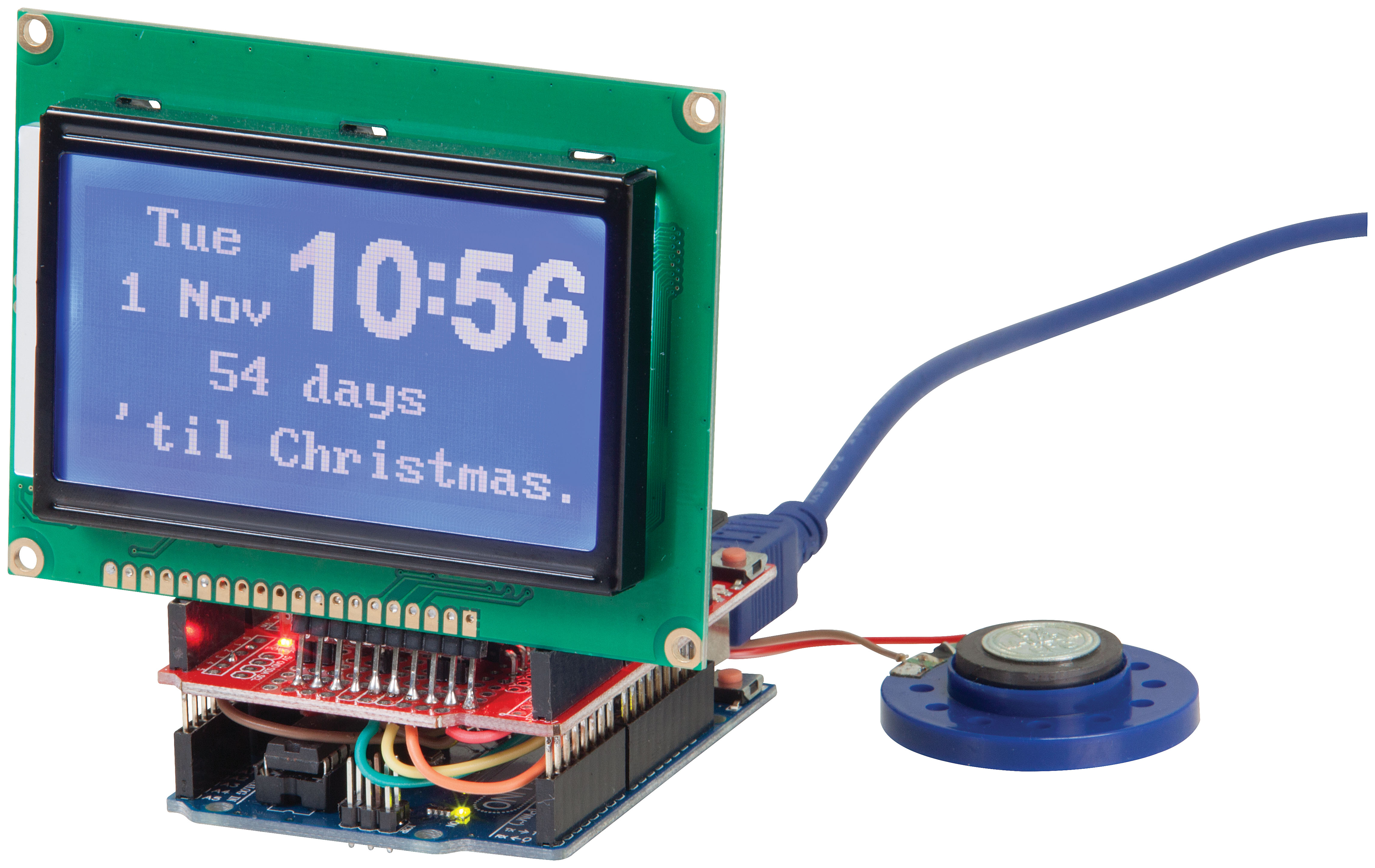
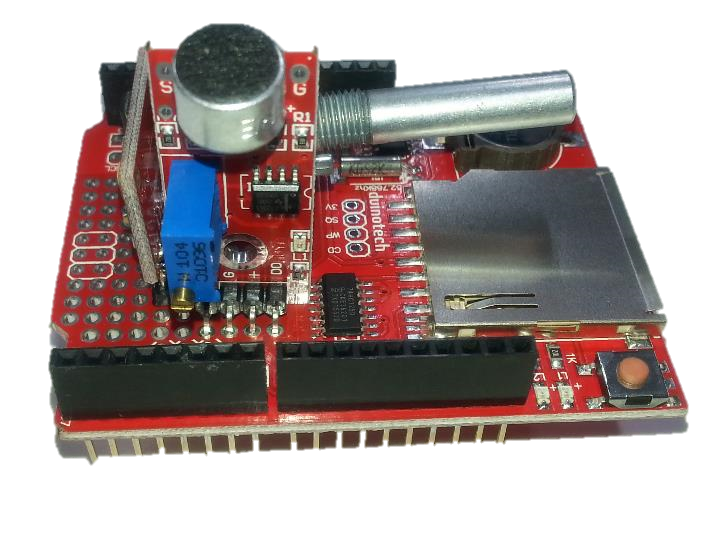
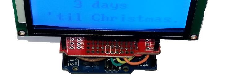
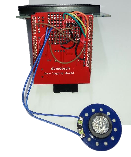
This project probably has the most parts of any of the ones we have done but is sure to help spread some Christmas joy. It's a clock which displays the time and date, and also displays the number of days until Christmas. When the sound module is triggered a voice (it might be Santa) announces the number of days and weeks until Christmas and then offers a Christmassy greeting. It's sure to keep everyone entertained. There is some soldering and careful assembly required to compete this project.
Materials Required
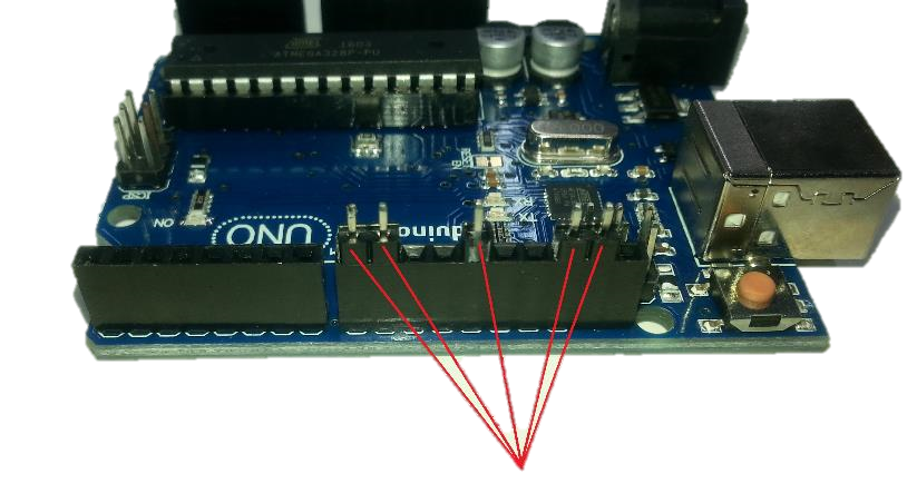
| 1 | Duinotech UNO r3 Main Board | XC4410 |
| 1 | ||
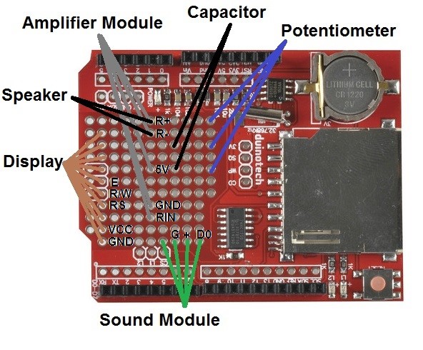
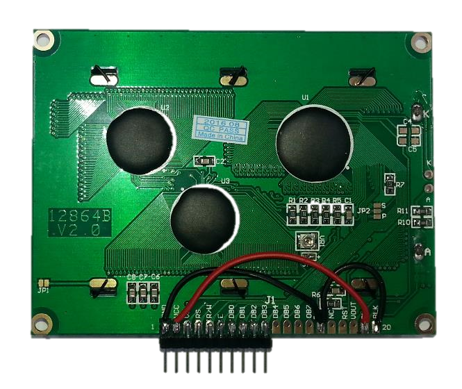
| 1 | Arduino Compatible 128x64 Dot Matrix LCD Display Module | XC4617 |
| 1 | Arduino Compatible Microphone Sound Sensor Module | XC4438 |
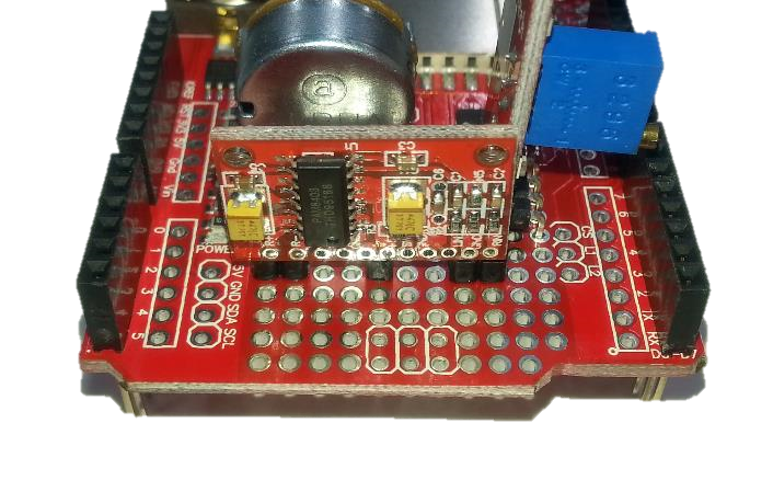
| 1 | Arduino Compatible 2 x 3W Amplifier Module | XC4448 |
| 1 | 1k Ohm Linear (B) Single Gang 16mm Potentiometer | RP7504 |
| 1 | 100nF 100VDC MKT Polyester Capacitor | RM7125 |
| 1 | 40 Pin Header Terminal Strip | HM3212 |
| 1 | 40mm All Purpose Replacement Speaker | AS3004 |
| 1 | 2GB Class 4 microSD Card | XC4998 |
Table of Contents
.png?branch=prod_main)
Similar projects you may be interested in
