First step is to put the micro:bit into the breakout board as shown.
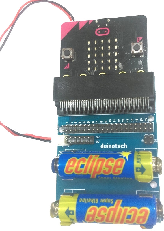
You must make sure the batteries are facing the same direction as the picture under the battery holder. Connect the power lead from the board up to the power connector on the micro:bit and turn the breakout board on. You should see the micro:bit come to life.
If you look closely at the breakout board, you will see each of the pins are labelled as shown:
.jpg?branch=prod)
The pins are labelled from 0 -> 16, which is what we will connect one lead of the LED to, then we will plug the other lead to one of either 0v or 3v
Making the card
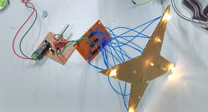
Find a nice picture online that you want to light up with LED lights. Here we used a picture of a tree from google images, but you can use anything. You will also need a small piece of firm cardboard, from a small box or similar, to poke the LEDs into.
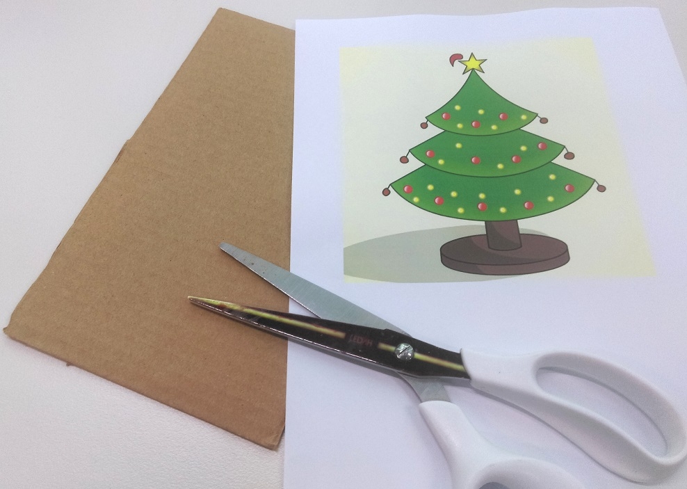
cut out this image and stick it to the cardboard so that the surface and well glued to the cardboard.
Now is where we will use the knife to cut a small hole to push the LEDs through.
Start by making a small x shape where you want the LED to go. being gentle and slow is key here so that you do not make the hole too big, about the size of the LED is the correct size.
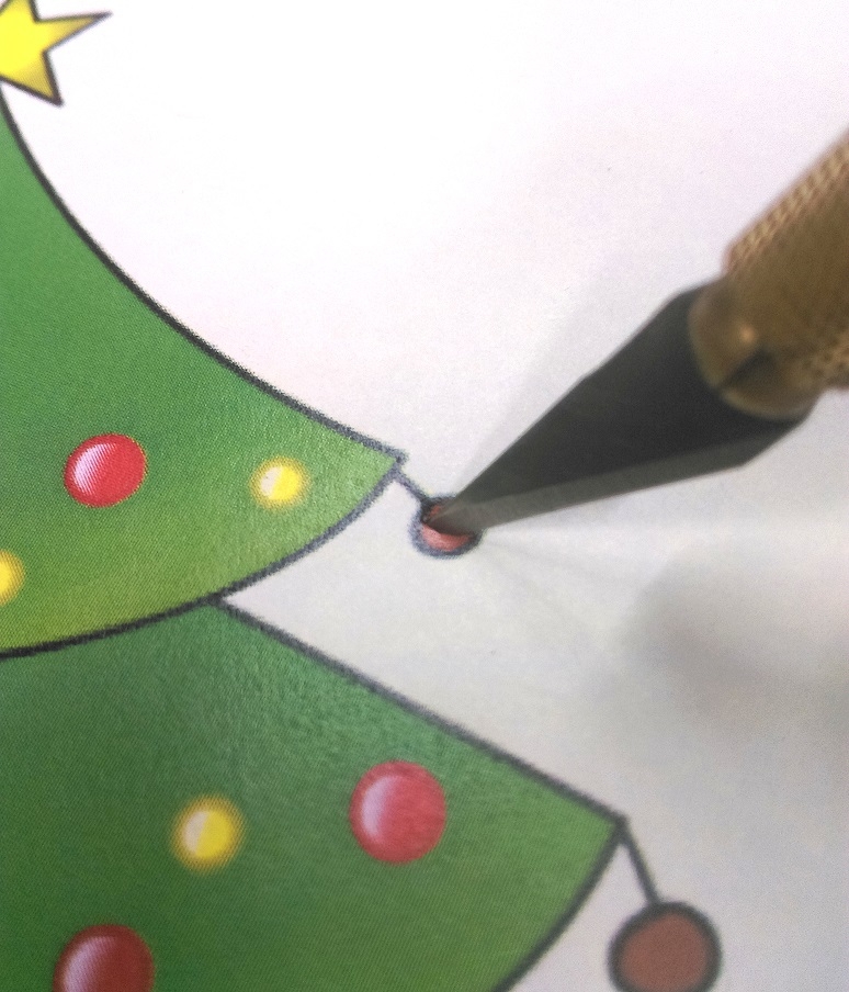
Once the x marks the spot, it is generally better to first push the LED in through the front of the face, so that the cardboard curls towards the back of the card, such as shown:
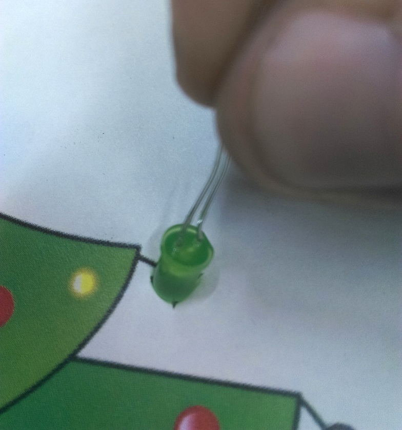
When viewed from the back, we can see the cardboard has bent through, which shows on the back of the board, rather than the front.
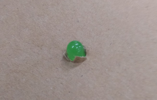
Once the LED is in this way, twist and slide it out, and you should find that the cardboard will retain it's shape and maintain a nice clean hole for you to slide the LED in through the proper way.
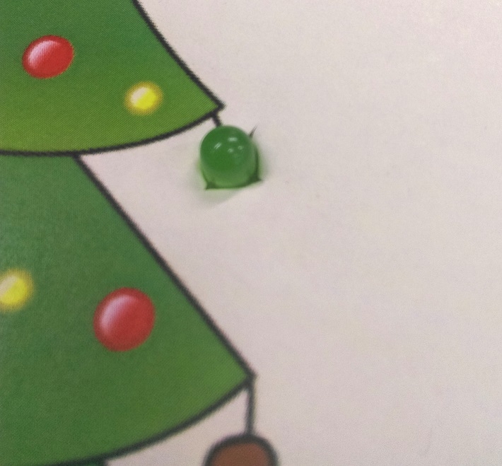
Likewise, the cardboard cut-outs are now behind the face, not getting in the way of the picture.
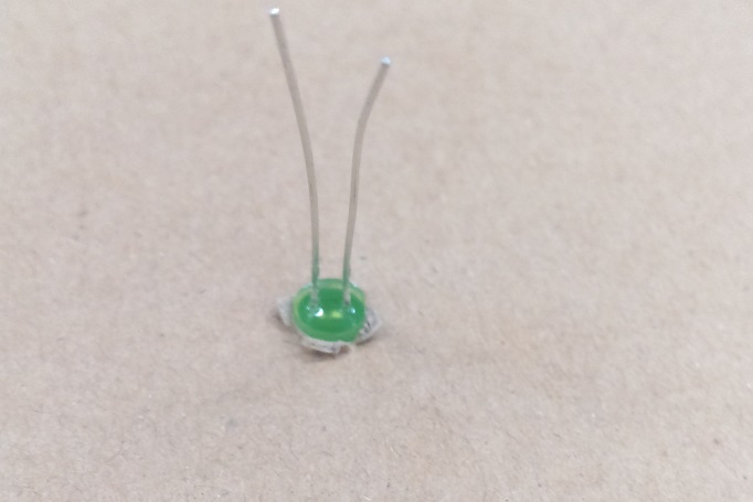
From here, you can simply bend the LED leads down to lay flat on the board. Pull off 2 wires from your jumper leads (WC6026) to slide onto the legs of the LED, remembering which leg is longer than the other.
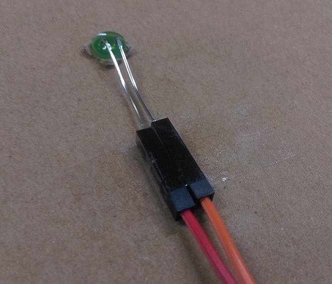
LEDs need to be connected in the right way; The longer leg is the positive connection for the LED, which will turn on when there is voltage.
Below, we have connected the positive to Pin0 and the negative to 0v.
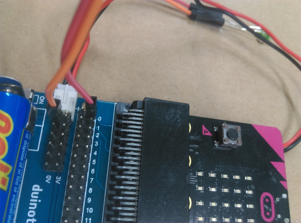
You can do this for the first 6 LEDs. When you want to connect more LEDs but do not have any 0v connections available, you will be able to connect the to the 3v connection and the negative to any of the pins.
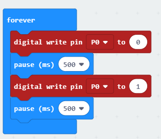
(We will explain how to turn these on in the programming section below.)


.jpg?branch=prod)




.jpg?branch=prod&format=webp&width=428)