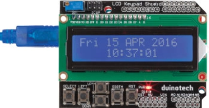
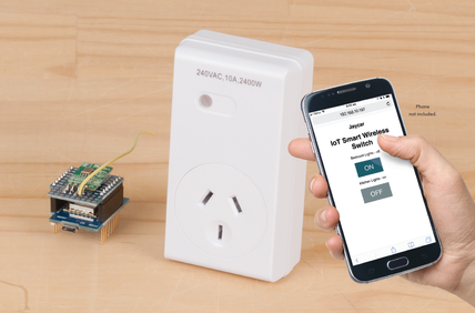
We have provided a cutout file for both of our projects this month, so feel free to print out (or, if you're very nice, you can ask the store to print out for you) a cutout sheet, and use some cheap glue to keep the paper in place while you drill and cut into the Jiffy enclosures. This will help get the sizes just right.
cutout.pdf
There's not a lot of work for this project, the main concerns are related to cutting out the jiffy box. Use the cut-outs to help get the sizes just right, then drill out the corners and slide in either some sort of band-saw or nibbler.
While we haven't used it, we've heard post-humorously that the TH1768 is great for this, and we'll be trying it next time we're modifying a Jiffy box.
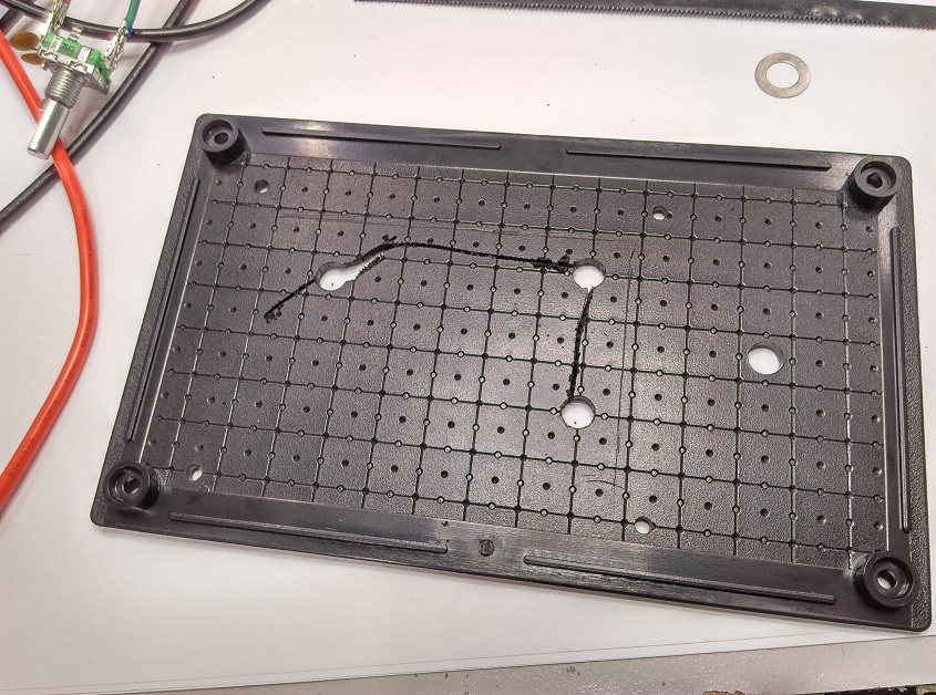
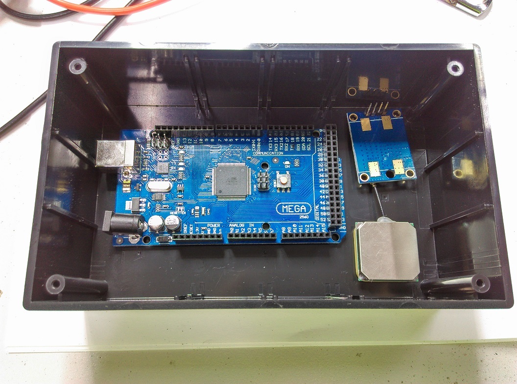
Position where you want, We've opted to have the mega and GPS in the enclosure, with the screen and encoder mounted on the front panel, as shown.
.jpg?branch=prod)
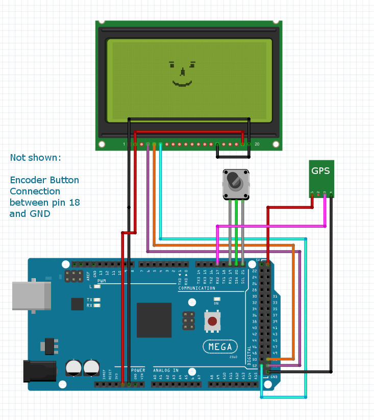
The GPS is mounted face down so we don't have to change the pins, and we just use the jumper leads to connect the modules to each other. At this point you'd probably want to drill out the 3mm holes and use some nuts and bolts to mount everything to the back of the case. Don't use the washers under the mega or GPS, as you'll need to use them for mounting the LCD panel. You could use some hot glue to glue down the GPS antenna.
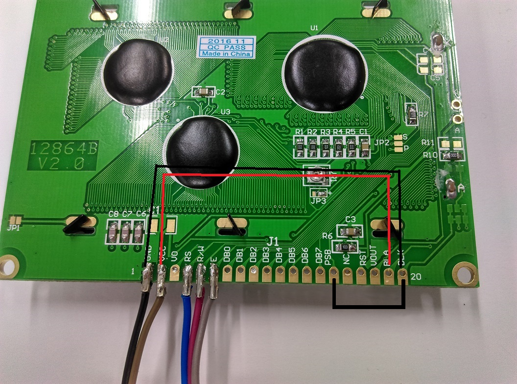
The LCD Panel does need jumper wires connecting 5V to BLA and GND to BLK as shown; also solder PSB to ground so that it is always enabled.
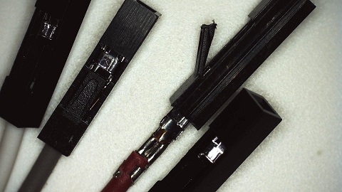
You can use a small pin or screwdriver to get in under the plastic of the sockets for the leads, and easily slide off the plastic.
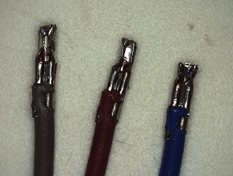
This will make for easy and neat soldering onto other components such as the encoder, and you can snip them to be a suitable size to mount onto the screen.
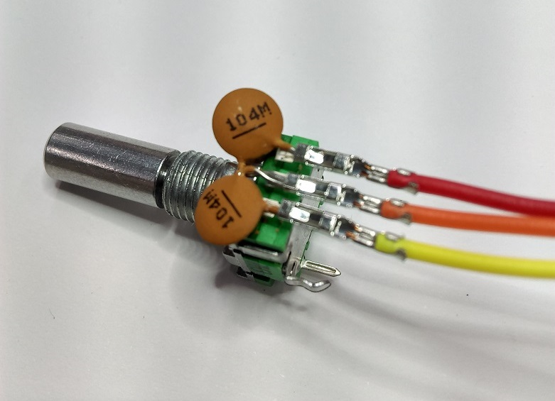
The encoder will need the two capacitors connected to it so that they can absorb the mechanical bounces and makes for a very smooth experience with the encoder. Attach these between pins A-C and B-C on the encoder. You can see the pinout diagram for the encoder below.

It will be easier if you first put on the sockets from before, then poke in the capacitor legs so that they all fit snug and tight, then apply a small dab of solder to join them all together.
The encoder requires a 10mm hole in the front case.
We've also soldered the DC jack to the DC jack on the MEGA, so that they can use the same regulator and have the reverse polarity protection. If you opt to use the DC Jack, ensure that the center pin is the positive (red) and the outside is negative (brown).
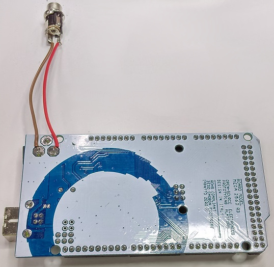
If you don't want to use a DC Jack, you can simply cut out a square hole for the MEGA's USB Connection.
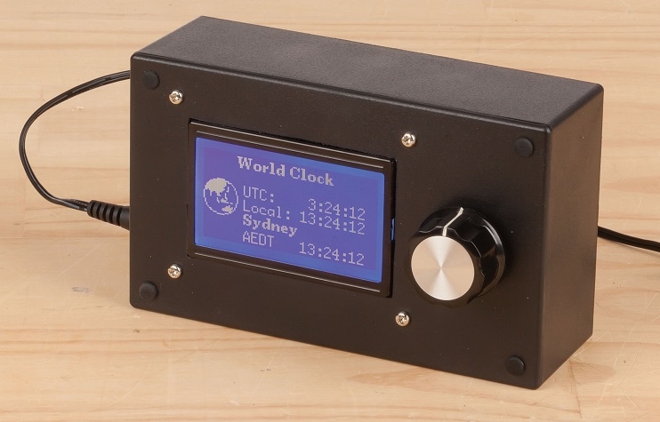
We opted not to include the Knob for this project, as we'll allow you to choose whatever you want. The knob in the picture is HK7742. But we have other styles and sizes for you to choose.



.jpg?branch=prod)


.jpg?branch=prod&format=webp&width=428)
